Eureka AIR delivers breakthrough ideas for toughest innovation challenges, trusted by R&D personnel around the world.

Actuator for a controlled coolant pump

A technology of cooling medium and actuator, applied in the direction of engine cooling, pump, pump device, etc., can solve the problem of delaying the rapid heating of the internal combustion engine, and achieve the effect of reducing the reliable function

Inactive Publication Date: 2013-12-04
SCHAEFFLER TECH AG & CO KG
View PDF13 Cites 9 Cited by
  • Summary
  • Abstract
  • Description
  • Claims
  • Application Information

AI Technical Summary

Problems solved by technology

The cooling medium thus circulates during a cold start of the internal combustion engine, thereby delaying the desired rapid heating of the internal combustion engine and the associated optimum operating temperature

Method used


Image

  • Actuator for a controlled coolant pump
  • Actuator for a controlled coolant pump
  • Actuator for a controlled coolant pump

Examples


Embodiment Construction

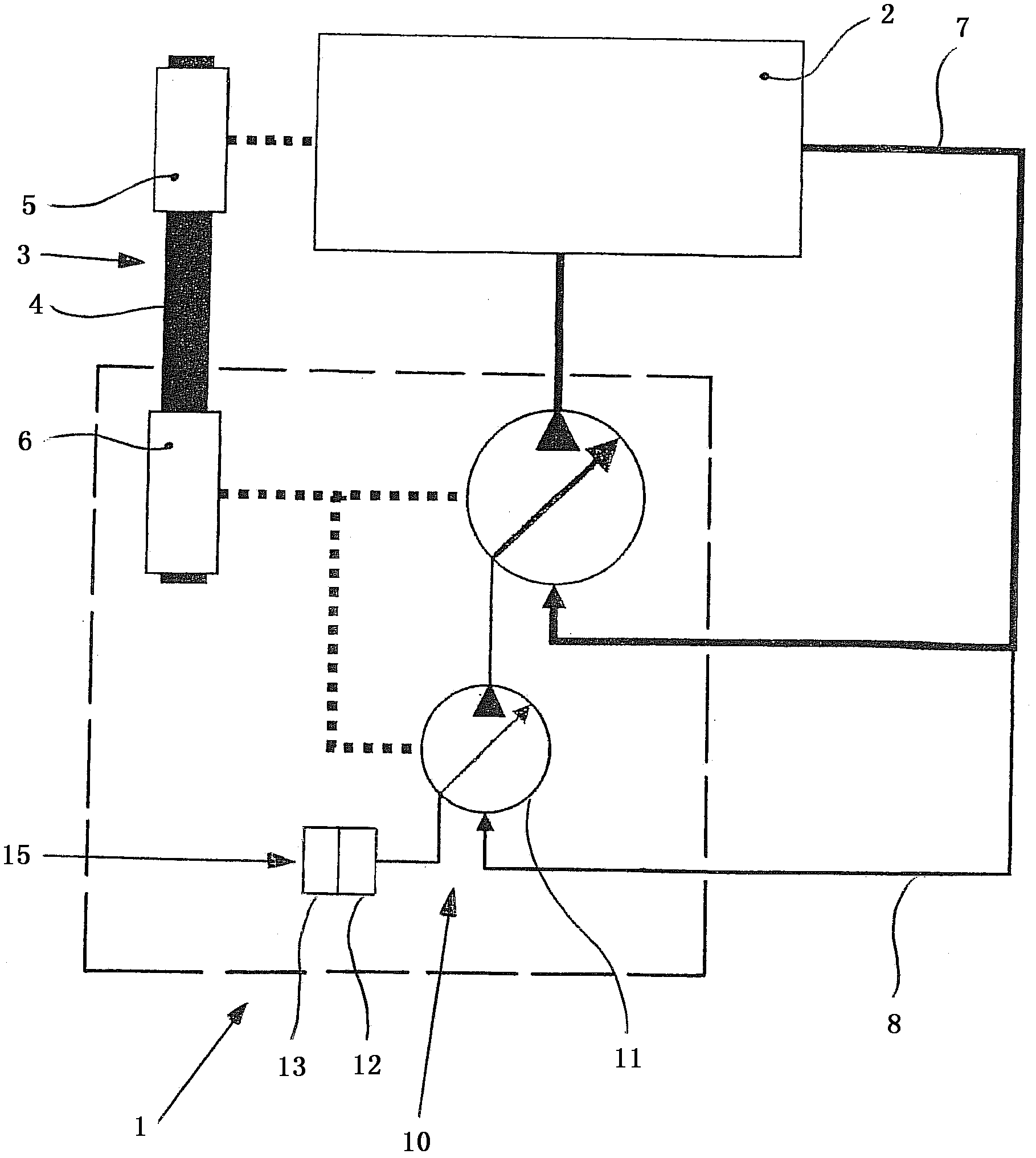
[0019] figure 1 All components of the regulated coolant pump 1 according to the invention are shown schematically. Coolant pump 1 , which is used specifically for cooling internal combustion engine 2 , is driven via traction drive 3 . The traction mechanism 4 of the traction drive 3 embodied as a belt drive connects a first belt pulley 5 , which is connected to a crankshaft (not shown) of the internal combustion engine 2 , to a second pulley 6 assigned to the coolant pump 1 . . The displacement or volume flow of the coolant pump 1 connected to the cooling circuit 7 can be adjusted or regulated by means of a hydraulically acting actuator 10 associated with the hydraulic circuit 8 and integrated in the coolant pump 1 . The structure of the actuator 10 comprises an eccentrically adjustable radial piston pump 11 cooperating with an actuating unit 15 comprising a linear free wheel 12 and a controllable adjustment element 13 .

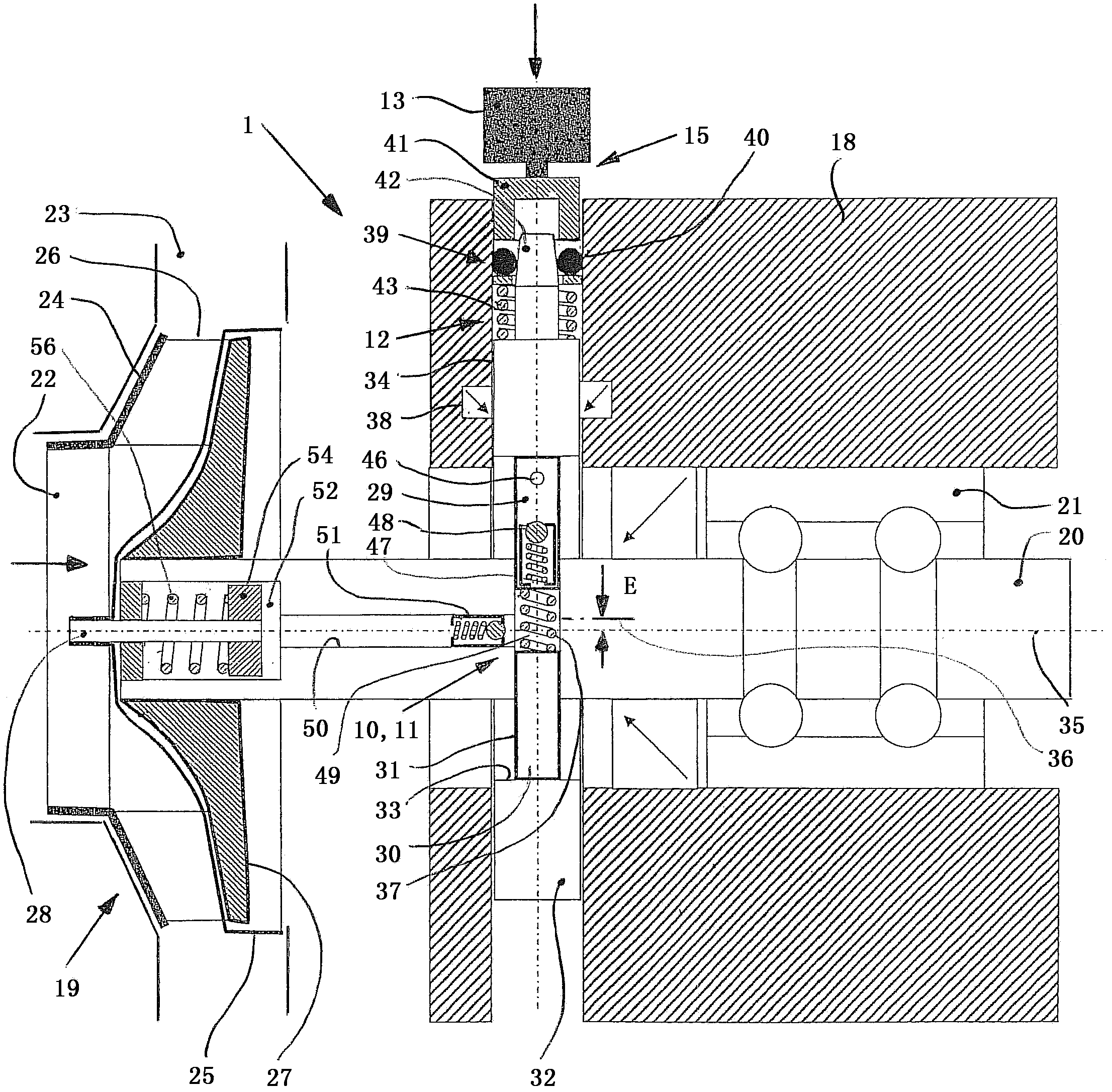
[0020] figure 2 The adjustable coolant pump 1 is ...


PUM


Abstract

A coolant pump of an internal combustion engine, with a pump housing and a hollow shaft rotatably mounted therein. Coolant is delivered via an impeller wheel from a suction connection. The flow is controlled by a guide plate on the impeller wheel that is variably displaceable axially between two end positions. The guide plate is adjustable by a push rod actuator guided in the pump shaft. The actuator has a radial piston pump integrated within the coolant pump with an intake piston and a counterpiston guided in the pump shaft, that are inserted lying opposite one another and delimit a pressure space. The pistons are enclosed outside by a linearly displaceable control element guided in the pump housing. Adjustment of the control element takes place as a function of a rotary angle of the pump shaft via an actuator unit having an electrically operated actuating element and a linear freewheel.

Description

technical field [0001] The invention relates to a regulated coolant pump for an internal combustion engine having an arrangement according to the features of the preamble of claim 1 . Background technique [0002] In liquid-cooled, in particular water-cooled, internal combustion engines, cooling water is guided in a closed circuit through the cooling channels of the crankcase and cylinder head and is subsequently cooled back in an air-to-water heat exchanger or cooler. To support the circulation of the cooling medium, cooling medium pumps are used, which are directly driven, in particular via belt drives. Due to the direct coupling between the coolant pump and the crankshaft, the pump speed is dependent on the speed of the internal combustion engine. The cooling medium thus circulates during a cold start of the internal combustion engine, thereby delaying the desired rapid heating of the internal combustion engine and the associated optimum operating temperature. In order ...

Claims


Application Information

Patent Timeline
Patent Type & Authority Applications(China)
IPC IPC(8): F04D15/00F01P5/10
CPCF04D13/12F04B49/005F04D15/0038F05D2270/64
Inventor 马库斯·波普安德烈亚斯·内德尔
Owner SCHAEFFLER TECH AG & CO KG
Why Eureka
Eureka Blog
Learn More