Fully bonded cement mortar bolt and grouting method
A cement mortar and full bonding technology, which is applied in the direction of foundation structure engineering, construction, and sheet pile walls, etc., can solve the problems that the quality of anchor bolts cannot be guaranteed, the installation speed of anchor bolts is slow, and mortar waste, etc., and the quality of anchor bolts is easy Guaranteed, reliable grouting fullness, convenient and safe construction
- Summary
- Abstract
- Description
- Claims
- Application Information
AI Technical Summary
Problems solved by technology
Method used
Image
Examples
Embodiment 1
[0025] Such as figure 1 , 4 Among them, a fully bonded cement mortar bolt includes a bolt body 1, and an exhaust pipe is arranged on the bolt body 1. With this structure, after the anchor rod body 1 is inserted into the anchor rod hole 6, the gas in the anchor rod hole 6 is discharged during the grouting process, so as to realize the construction of inserting the anchor rod first and then grouting.
Embodiment 2
[0027] On the basis of Embodiment 1, in an optional solution, the exhaust pipe is an outer exhaust pipe 2 , and the outer exhaust pipe 2 is fixed on the outer wall of the bolt body 1 by a fixing clip 3 . In this example, the outer exhaust pipe 2 is made of a soft plastic pipe with an inner diameter of 4-5 mm and a wall thickness of 1-1.5 mm. The soft plastic pipe has a surplus length of not less than 50cm at the outer end of the anchor rod body 1, and the soft plastic pipe is fixed firmly and smoothly without damage and joints, and the exhaust is unobstructed.
[0028] Further optimization schemes such as figure 2 , 3 Among them, the outer end of the outer exhaust pipe 2 exceeds the outer end of the anchor rod body 1, and the inner end of the outer exhaust pipe 2 is flush with the inner end of the anchor rod body 1. Preferably, the outer exhaust The inner end of the pipe 2 is provided with an inclined plane to facilitate exhaust. With this structure, the outer exhaust pipe...
Embodiment 3
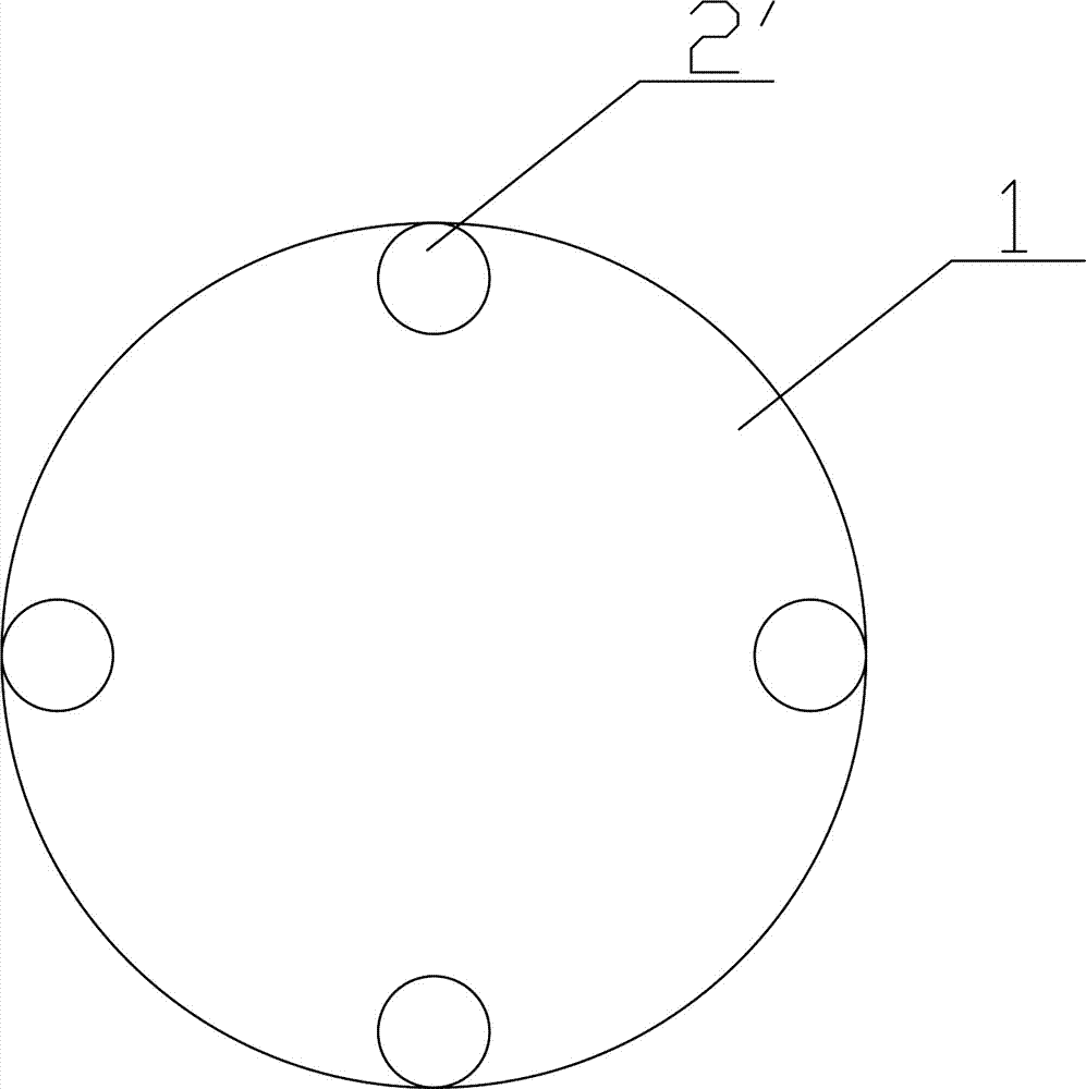
[0030] On the basis of Example 1, another optional scheme such as Figure 3~5 Among them, the exhaust pipe is the inner exhaust pipe 2'. As a result, the structure is more compact, and compared with the second embodiment, the outer exhaust pipe 2 is also prevented from affecting the bonding stress.
[0031] In a further optimized solution, the internal exhaust pipe 2' is a groove located on the outer wall of the anchor rod body 1, and is formed by closing the top. Firstly, a groove is pressed out on the anchor rod body 1 by cold pressing or hot pressing, the depth of the groove is greater than the width of the groove, and then the surface of the anchor rod is induction heated to 700-1200°C and then extruded to make the top of the groove Closed to form an inner exhaust pipe 2', the cross section of which is as image 3 , 5 As shown in , if more grooves are used, the diameter of each groove can be made smaller, even if part of the grooves, that is, the inner exhaust pipe 2' i...
PUM
 Abstract
Description
Claims
Application Information
 - R&D
- Intellectual Property
- Life Sciences
- Materials
- Tech Scout
- Unparalleled Data Quality
- Higher Quality Content
- 60% Fewer Hallucinations
Browse by: Latest US Patents, China's latest patents, Technical Efficacy Thesaurus, Application Domain, Technology Topic, Popular Technical Reports.
© 2025 PatSnap. All rights reserved.Legal|Privacy policy|Modern Slavery Act Transparency Statement|Sitemap|About US| Contact US: help@patsnap.com


