Connecting device

A connecting device and cylinder technology, applied in the direction of connecting components, mechanical equipment, etc., can solve the problems of deformation and falling off of the contact surface

Inactive Publication Date: 2013-12-04
付云波
View PDF0 Cites 0 Cited by
  • Summary
  • Abstract
  • Description
  • Claims
  • Application Information

AI Technical Summary

Problems solved by technology

For example, a drill rod with a diameter of 140mm may withstand an impact energy of more than 4500kj, and common connecting devices such as welding and threading cannot withst...

Method used


Image

  • Connecting device
  • Connecting device
  • Connecting device

Examples


Embodiment Construction

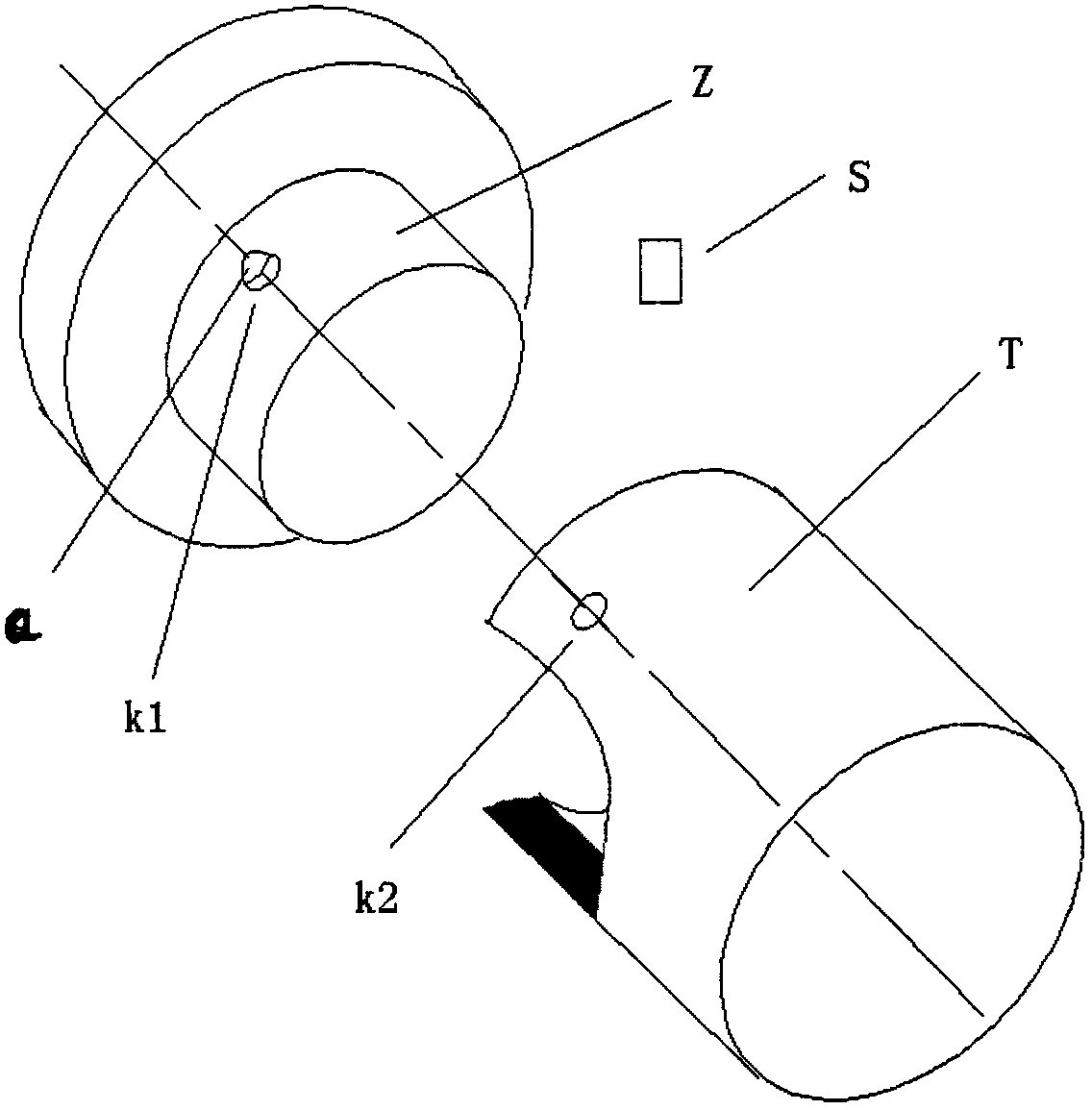
[0008] exist figure 1 Among them, there is a circular hole K1 and a curved surface Q on the connecting device cylinder Z, and a circular hole K2 on the connecting device cylinder T, and the lock pin S is inserted in the circular holes K1 and K2.

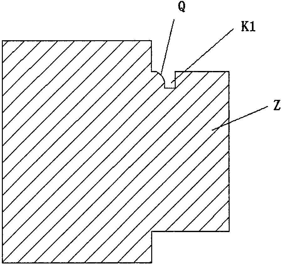
[0009] exist figure 2 Among them, the connecting device cylinder Z has a circular hole K1 perpendicular to the axial direction, and the diameter of the circular hole K1 gradually increases on the side of the cylinder Z close to the part, forming a curved surface Q.

[0010] exist image 3 , the lock pin S is a cylinder.

[0011] exist Figure 4 , the cylinder Z extends into the cylinder T, the round hole K1 on the lock pin cylinder Z is aligned with the round hole K2 on the cylinder T, and the lock pin S is inserted, and the applied opposite force makes the lock pin S The deformation rests on the surface Q.


PUM


Abstract

The invention discloses a connecting device for metal parts. The connecting device comprises a lock pin (S) capable of achieving plastic deformation under force, a cylinder (Z) reserved on one part and a drum (T) reserved on the other part, wherein a circular hole (K1) perpendicular to the axial direction is formed in the cylinder, the diameter of the circular hole (K1) increases gradually on the side of the cylinder (Z), which is close to the part, to form a curved surface (Q), and a circular hole (K2) perpendicular to the axial direction is reserved in the wall of the drum (T). When the two parts are connected, the cylinder (Z) extends into the drum (T), the lock pin (S) is enabled to be align to and inserted in the circular hole (K1) of the cylinder (Z) and the circular hole (K2) of the drum (T), then, an opposite force is exerted to enable the lock pin (S) to deform to abut against the curved surface (Q) to complete the connection. According to the mode, a cheap and convenient mounting mode, such as mounting of milling machine drills and abrasion-resistant protective hoods of hydraulic breakers, is provided for metal parts gone through unidirectional strong impact and occasions allowing unidirectional small-scale deformation to form an effect of increasing tightness by clamping.

Description

technical field [0001] The invention proposes a connecting device for connecting two metal parts. Background technique [0002] There are many types of connecting devices for metal parts, but in some occasions, metal parts are subjected to a huge impact force in a single direction, but the force in other directions is not large, such as the wear-resistant protective head cover of the hydraulic breaker drill rod For the connection, only the force from the breaking hammer along the axis of the chisel to the broken object is extremely large, and there is no force in other directions during work, as long as the connection of the parts is maintained. For example, a drill rod with a diameter of 140mm may withstand an impact energy of more than 4500kj, and common connecting devices such as welding and threading cannot withstand such a huge impact force; The surface deformation is very serious, and some connecting devices such as bayonet pins will produce a large gap, resulting in ...

Claims


Application Information

Patent Timeline
IPC IPC(8): F16B21/04
Inventor 付云波
Owner 付云波
Why Eureka
Try Eureka