
Electromagnetic valve and refrigerating device provided with electromagnetic valve

A refrigeration device and solenoid valve technology, which is applied to valve operation/release devices, valve devices, refrigerators, etc., can solve the problems of increased weight of refrigeration devices, cumbersome installation procedures, high manufacturing costs, etc. The installation process is simple and the effect of reducing the installation process

Active Publication Date: 2013-12-04
浙江三花商用制冷有限公司
View PDF3 Cites 7 Cited by
  • Summary
  • Abstract
  • Description
  • Claims
  • Application Information

AI Technical Summary

Problems solved by technology

[0005] The deficiency of the flanged solenoid valve in the prior art refrigerating device is that, due to figure 1 The flanged solenoid valve in the refrigeration device shown has only one inlet channel and one outlet channel. Therefore, one solenoid valve can only control the on-off of two chambers of the compressor. When there are multiple chambers in the refrigeration compressor, Such as three chambers - when entering chamber, compression chamber and discharge chamber, in order to realize the on-off control of the three chambers on the compressor, two solenoid valves must be used. In this way, at first, the weight of the refrigeration device increases and the The manufacturing cost is high, and secondly, the installation process is cumbersome

Method used


Image

  • Electromagnetic valve and refrigerating device provided with electromagnetic valve
  • Electromagnetic valve and refrigerating device provided with electromagnetic valve
  • Electromagnetic valve and refrigerating device provided with electromagnetic valve

Examples


Embodiment Construction

[0027] Below in conjunction with accompanying drawing, principle of the present invention is described in detail as follows:

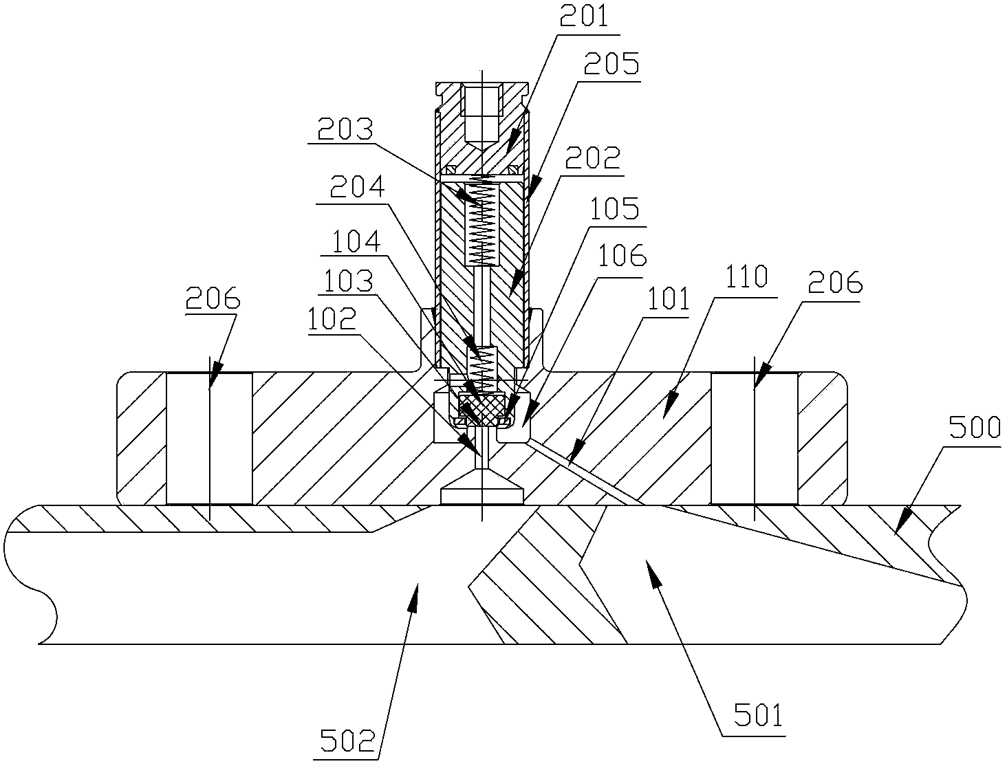
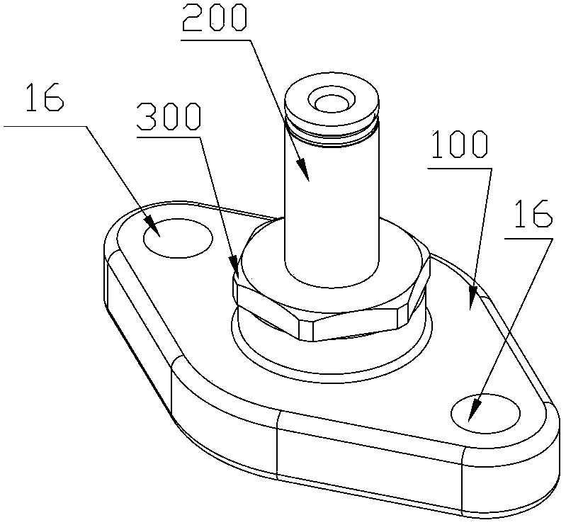
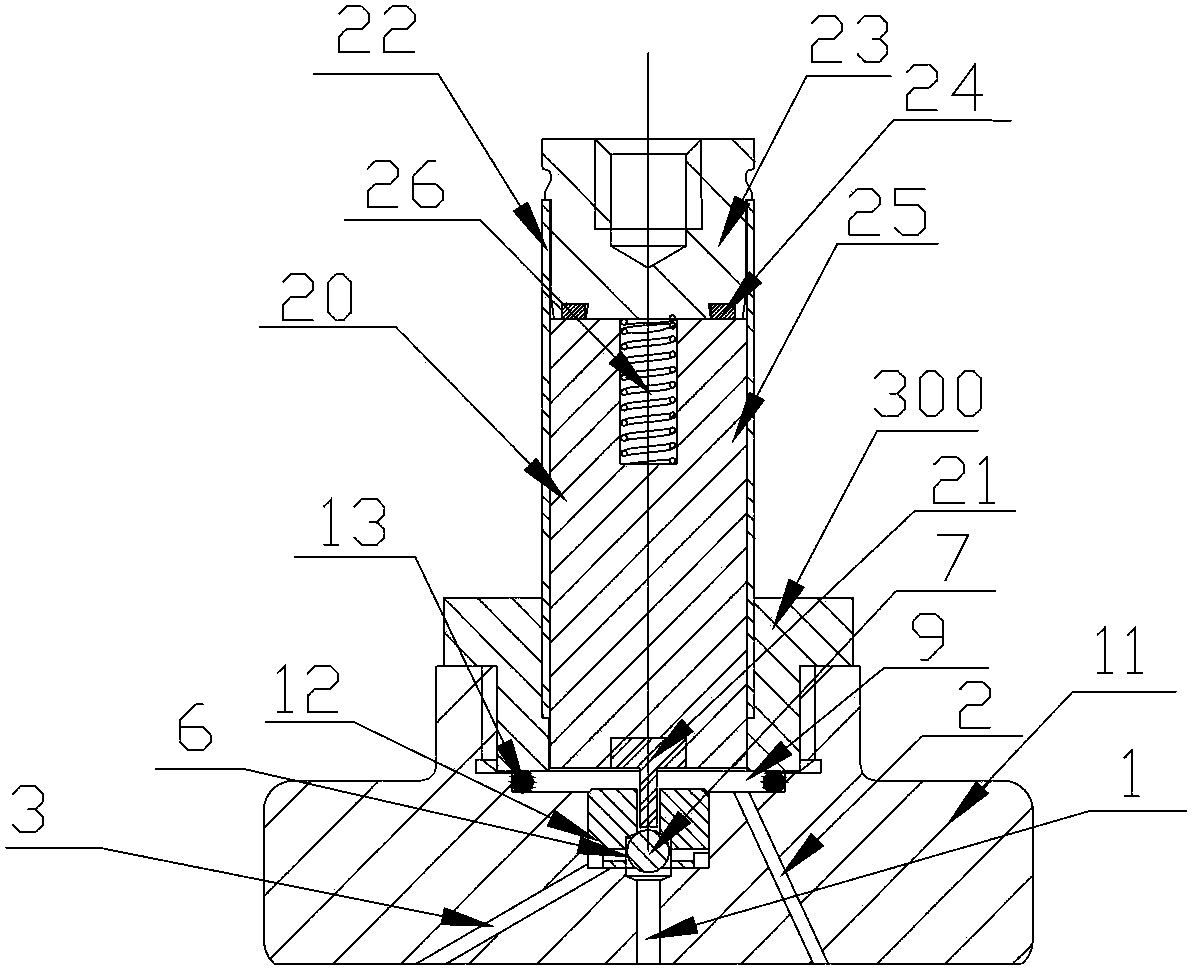
[0028] figure 2 It is a perspective view of an embodiment of the solenoid valve of the present invention; image 3 for figure 2 Sectional view of the solenoid valve shown with the main valve port open; Figure 4 for image 3 Sectional view of the main valve seat of the middle solenoid valve; Figure 5 for image 3 The cross-sectional view of the secondary valve seat of the middle solenoid valve; Image 6 for figure 2 The cross-sectional view of the solenoid valve with the main valve port closed.

[0029] Such as figure 2 As shown, in an embodiment of the solenoid valve of the present invention, the solenoid valve includes a driving device 200 and a valve seat assembly 100, and the driving device 200 and the valve seat assembly 100 pass through a connecting piece 300 (this embodiment is specifically a connection with an external thread nut)...


PUM


Abstract

The invention discloses an electromagnetic valve which comprises a valve seat assembly and a driving device, wherein the valve seat assembly is provided with a flow-in channel and a flow-out channel, and the driving device is fixedly connected to the valve seat assembly. The electromagnetic valve is characterized in that the valve seat assembly comprises a main valve seat and an auxiliary valve seat, wherein the main valve seat is provided with a main valve opening, and the auxiliary valve seat is fixedly connected with the main valve seat and is provided with an auxiliary valve opening; a valve cavity is formed between the main valve opening and the auxiliary valve opening, and a valve element for opening or closing the main valve opening or the auxiliary valve opening is arranged inside the valve cavity; the flow-out channel is communicated with the auxiliary valve opening, and the flow-in channel is communicated with the main valve opening; the valve seat assembly further comprises a bypass channel communicated with the valve cavity; when the main valve opening is opened but the auxiliary valve opening is closed, the bypass channel is communicated with the flow-in channel; when the auxiliary valve opening is opened but the main valve opening is closed, the bypass channel is communicated with the flow-out channel. The invention further discloses a refrigerating device provided with the electromagnetic valve.

Description

technical field [0001] The invention relates to the technical field of fluid flow direction control in refrigeration systems. In particular, it relates to a solenoid valve and a refrigeration device using the solenoid valve. Background technique [0002] In a vapor compression refrigeration device, the compressor is one of the main components. The compressor compresses the refrigerant vapor from a low-pressure state to a high-pressure state, creating the conditions for the refrigerant liquid to be refrigerated at low temperature in the evaporator and liquefied at room temperature in the condenser. In addition, because the compressor continuously inhales and discharges gas, the refrigeration cycle can be repeated, so it is called the "heart" of the entire device. In order to accurately control the flow direction of the fluid in the compressor, more and more solenoid valves are used on the compressor. [0003] Such as figure 1 Shown is a structural schematic diagram of a r...

Claims


Application Information

Patent Timeline
IPC IPC(8): F16K1/00F16K1/14F16K1/42F16K31/06F25B41/04F25B41/20
Inventor 不公告发明人
Owner 浙江三花商用制冷有限公司
Features
  • Generate Ideas
  • Intellectual Property
  • Life Sciences
  • Materials
  • Tech Scout
  • Unparalleled Data Quality
  • Higher Quality Content
  • 60% Fewer Hallucinations
Learn More