Method for achieving synchronous collection of multiple devices through single-channel analogue signal

A technology for synchronous acquisition and analog signal, applied in the direction of synchronization device, measurement device, instrument, etc., can solve the problem of affecting the accuracy of analog signal acquisition, affecting the synchronization accuracy between devices, and phase delay error between signals, so as to avoid high-frequency digital interference. Noise influence, good usability, effect of avoiding phase delay errors

Active Publication Date: 2013-12-04
VI SERVICE NETWORK
View PDF6 Cites 5 Cited by
  • Summary
  • Abstract
  • Description
  • Claims
  • Application Information

AI Technical Summary

Problems solved by technology

Since two independent signal links need to be used for transmission between devices, there is a problem of phase delay error between signals, which affects the synchronization accuracy between devices
At the same time, because most of the synchronous acquisition systems are analog signal acquisition, in order to achieve synchronization between multiple devices, it is necessary to add a digital module for each device to achieve synchronization, which increases the system overhead
In addition, the high-frequency noise of digital equipment may also affect the acquisition accuracy of analog signals, thereby affecting the overall performance of the system

Method used


Image

  • Method for achieving synchronous collection of multiple devices through single-channel analogue signal
  • Method for achieving synchronous collection of multiple devices through single-channel analogue signal
  • Method for achieving synchronous collection of multiple devices through single-channel analogue signal

Examples


Embodiment 1

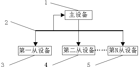
[0025] The method of the invention is used to realize synchronous collection of three devices. The collection devices are master device 1 , first slave device 3 and second slave device 4 respectively. The first acquisition module 10, the second acquisition module 14 and the third acquisition module 17 are all NI 9232, the first controller 9, the second controller 13 and the third controller 16 are all NI 9025, the first chassis 8, the third Both the second chassis 12 and the third chassis 15 are NI 9118, and the analog output module 11 is NI 9263.

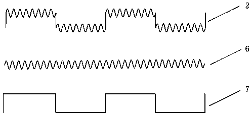
[0026] The analog output module 11 in the master device 1 produces a single analog composite signal 2, which is sent to the master device 1, the first slave device 3 and the second slave device 4 at the same time, the first acquisition module 10 of the master device 1, the first slave device The second collection module 14 of the device 3 and the third collection module 17 of the second slave device 4 respectively receive and coll...


PUM


Abstract

The invention belongs to the synchronous collection technology of the technical field of test and measurement and particularly relates to a method for achieving synchronous collection of multiple devices through a single-channel analog signal. The method for achieving synchronous collection of the multiple devices through the single-channel analog signal comprises the following steps that an analog composite signal generated by the main device is transmitted to each auxiliary device and an analog collection channel of the main device simultaneously; each device conducts analog collection, local reference clock extraction and trigger signal extraction on the analog composite signal, so that a local reference clock and a trigger signal are obtained; the local reference clock is used as a sampling clock of each device, the trigger signal is used as a collection start control signal of each device, and therefore synchronous collection of the multiple devices is achieved. The method for achieving synchronous collection of the multiple devices through the single-channel analog signal is simple in form. Compared with an existing two-channel digital signal synchronizing method, the method for achieving synchronous collection of the multiple devices through the single-channel analog signal is more economical, more convenient to operate, more reliable, better in practicability, and capable of being popularized and being applied to various applications which need multichannel signal transmission between devices.

Description

technical field [0001] The invention belongs to the synchronous acquisition technology in the technical field of test and measurement, and in particular relates to a method for realizing multi-device synchronous acquisition by using a single-channel analog signal. Background technique [0002] In industrial measurement and control applications, due to the large number of test points and scattered test points, it is often necessary to use multiple devices to complete on-site collection and monitoring; at the same time, due to the special needs of the application, for example, the vibration and noise monitoring system of large mechanical equipment , these scattered measuring points must be collected synchronously in order to conduct a complete and accurate analysis of the overall state of the equipment. The synchronous collection here not only requires all test channels to start collecting at the same time, but also requires all channels to share a clock signal. [0003] The ...

Claims


Application Information

Patent Timeline
Patent Type & Authority Applications(China)
IPC IPC(8): H04L7/00G01H17/00
Inventor 金玮邵晖彭泓张明涛覃剑欢
Owner VI SERVICE NETWORK
Why Eureka
Try Eureka