Route selection method and functional network element
A technology of network elements and functions, applied in the field of routing methods and functional network elements, to achieve the effect of reducing access pressure
- Summary
- Abstract
- Description
- Claims
- Application Information
AI Technical Summary
Problems solved by technology
Method used
Image
Examples
Embodiment 1
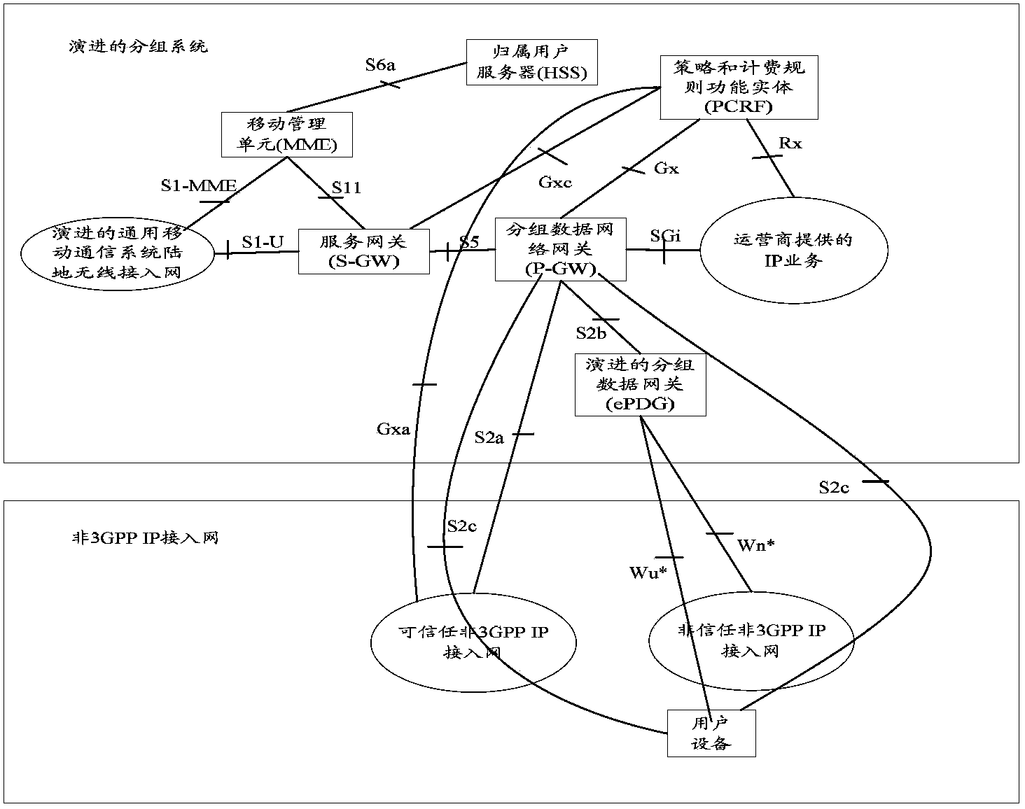
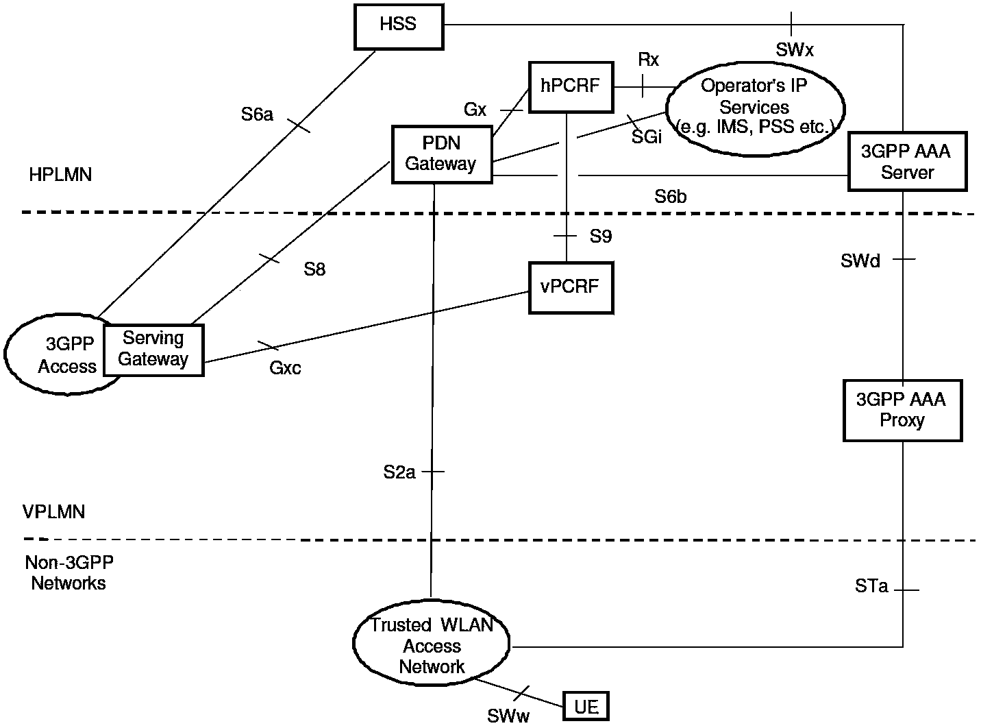
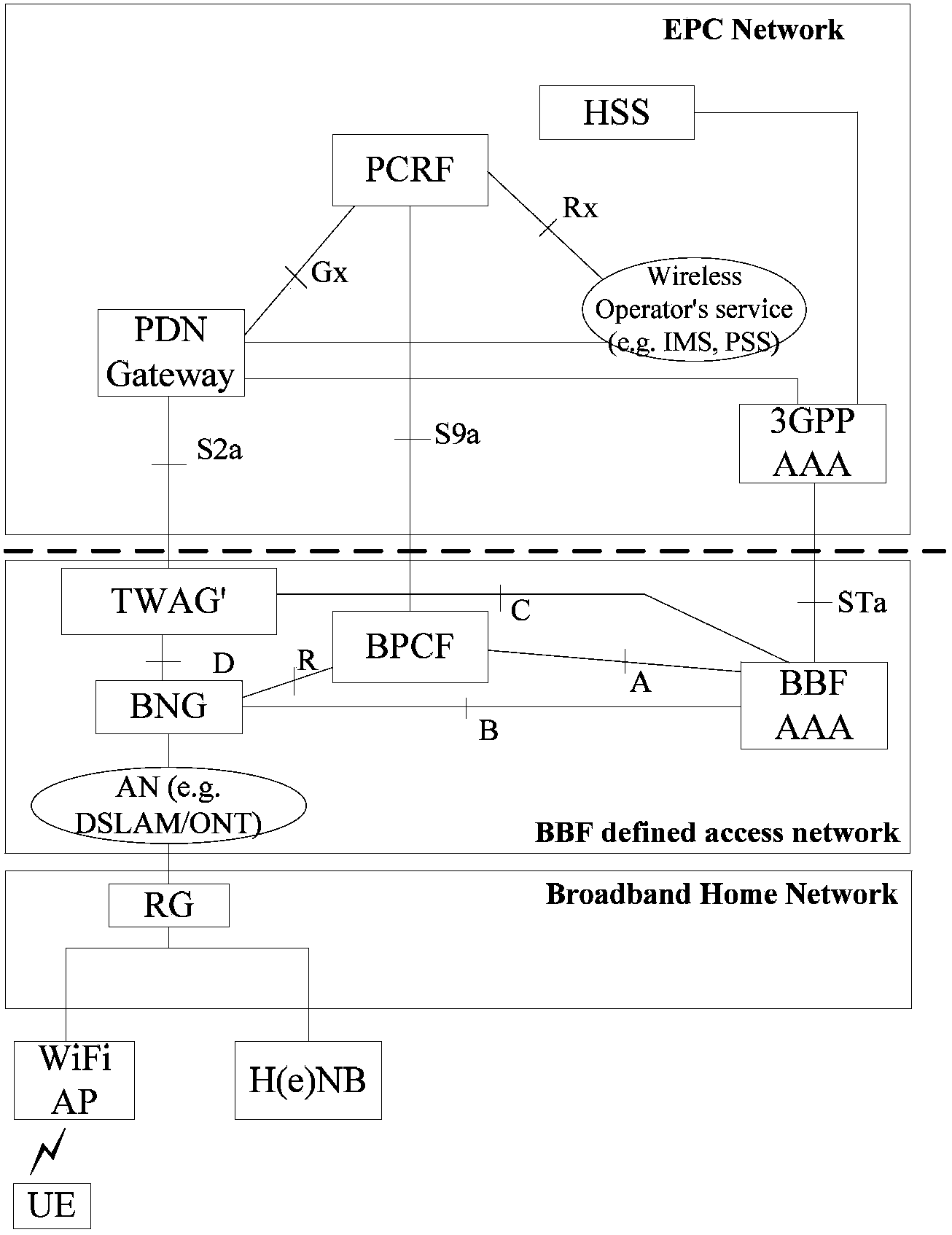
[0066] In this embodiment, it mainly describes the architecture diagram of the entire network when the UE accesses the EPC through a trusted WLAN. The central idea of this architecture is: in the WLAN network, a WLAN access gateway is added to be responsible for message exchange between the control plane and the user plane between the WLAN network and the EPC network.
[0067] The difference between the network elements involved in this architecture and the network elements involved in the existing access network access to the existing 3GPP network is that a TWAG' is added in the WLAN network: TWAG' is responsible for the connection between the WLAN network and the EPC network. Intercommunication of control plane messages and user plane data. image 3 After introducing TWAG' in the present invention, a schematic diagram of UE accessing EPC architecture 1 through the WLAN S2a interface, such as image 3 As shown, under this network architecture, the key interfaces involved a...
Embodiment 2
[0072] In this embodiment, the process of 3GPP UE accessing 3GPP EPC through WLAN is mainly described. Among them, the EAP authentication process needs to be forwarded to WLAN AAA through TWAG', AP / RG acts as the EAP authenticator, and AC / BNG and TWAG' act as AAA agents. When the AC / BNG receives the service type determined by the 3GPPAAAA as allowing access to the EPC, it executes this embodiment. Figure 4 It is a flow chart of UE accessing EPC based on architecture 1 in Embodiment 1 of the present invention through WLAN S2a interface, and the process of UE accessing EPC through WLAN S2a interface includes the following steps:
[0073] Step 401: The UE and the WLAN network element perform non-3GPP-specific procedures, such as: link establishment, etc.;
[0074] Step 402: The UE may send an EAPOL-START message to the AP / RG to request authentication;
[0075] Step 403-Step 404: The AP / RG, as the EAP authenticator, will trigger the EAP authentication process to the UE. Wherei...
Embodiment 3
[0092] In this embodiment, the process is similar to the process in embodiment 2, except that the AP / RG does not serve as the EAP authenticator, but the AC / BNG serves as the EAP authenticator, and the AP / RG cannot perceive the relevant EAP authentication process. For other processes, refer to the relevant description of Embodiment 2. For details, see Figure 5 The flow shown is described in detail as follows:
[0093] Step 501: The UE and the WLAN network element perform non-3GPP-specific procedures, such as: link establishment, etc.;
[0094] Step 502: UE may send an EAPOL-START message to AC / BNG to request authentication;
[0095] Step 503-Step 504: AC / BNG, as the EAP authenticator, will trigger the EAP authentication process to the UE. Wherein, the UE carries the NAI in the EAP-RES / Identity message. After AC / BNG receives the EAP-RES / Identity message encapsulated by AAA, it can first judge whether it is a 3GPP UE according to the authentication type. If the authenticatio...
PUM
 Abstract
Description
Claims
Application Information
 - R&D
- Intellectual Property
- Life Sciences
- Materials
- Tech Scout
- Unparalleled Data Quality
- Higher Quality Content
- 60% Fewer Hallucinations
Browse by: Latest US Patents, China's latest patents, Technical Efficacy Thesaurus, Application Domain, Technology Topic, Popular Technical Reports.
© 2025 PatSnap. All rights reserved.Legal|Privacy policy|Modern Slavery Act Transparency Statement|Sitemap|About US| Contact US: help@patsnap.com


