

Knitting machine
A technology of knitting machines and knitting machines, which is applied in knitting, weft knitting, textiles and papermaking, etc. It can solve the problems of accelerated wear, no longer ensuring the opening of the latch, and wear of the latch spoon at the top of the hook, and achieves narrow structure width. Effect
- Summary
- Abstract
- Description
- Claims
- Application Information
AI Technical Summary
Problems solved by technology
Method used
Image

Examples
Embodiment Construction
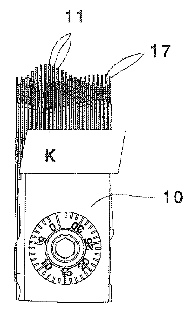
[0028] figure 1 Shown is the cylinder cam section 10 and the needle 11 engaging therewith (which is designed as a latch needle).
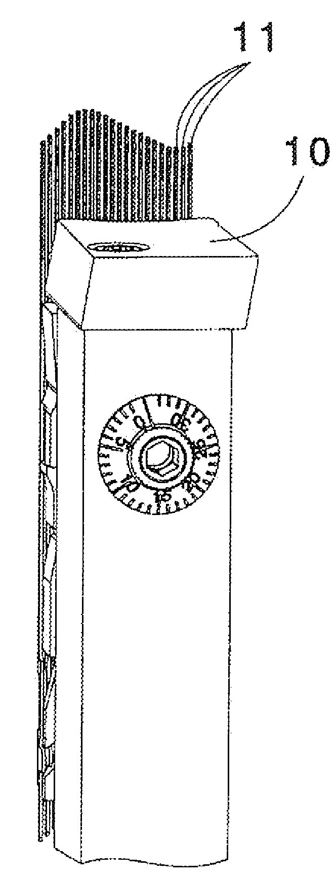
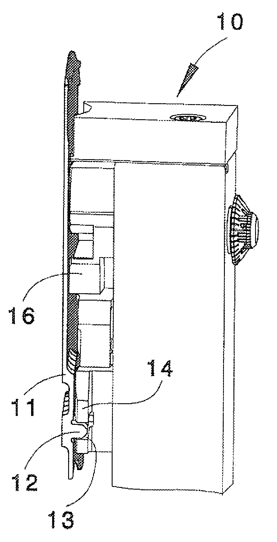
[0029] from in figure 2 In the side view of the cylinder cam section 10 in , it can be seen that the knitting needles 11 arranged parallel to one another in the grooves of the cylinder not shown in detail here have butts 12 which are in the needle control curve of the cam 14 13 to guide for controlling needle movement.
[0030] available through image 3 In the shape of the needle control curve identified in the detailed view of the triangle 14, the needle 11 performs the figure 1 Visible push-out and unwind movement. The cylinder cam, which is not shown in detail here, has a plurality of adjoining cylinder cam segments 10 of the same construction type, so that all needles of the syringe can be acted on in the same way by the cam 14 of the segment 10 . In the exemplary embodiment shown here, the cylinder cam section 10 is arranged radially ou...
PUM
 Abstract
Description
Claims
Application Information