
knitting machine

A knitting machine and latch needle technology, applied in the directions of knitting, weft knitting, textile and paper making, etc., can solve the problems of accelerated wear, no longer ensure the opening of the latch, and wear of the latch and key at the top of the hook, and achieve a narrow structure width. Effect

Inactive Publication Date: 2016-06-29
SIPRA PATENTENTWICKLUNGS & BET GMBH (DE)
View PDF12 Cites 0 Cited by
  • Summary
  • Abstract
  • Description
  • Claims
  • Application Information

AI Technical Summary

Problems solved by technology

The latch often hits the side of the hook tip, which causes further wear on the hook tip and / or the latch spoon
However, if the hook tip and the tongue tip are damaged, the opening of the latch is no longer ensured after the thread breaks while knitting
The use of natural yarns also accelerates this wear

Method used


Image

  • knitting machine
  • knitting machine
  • knitting machine

Examples


Embodiment Construction

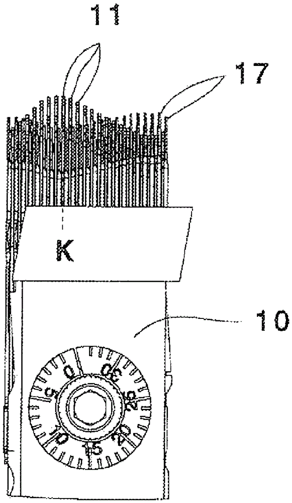
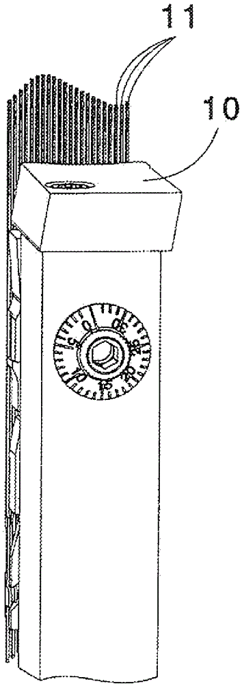
[0028] figure 1 Shown is the cylinder cam section 10 and the needle 11 engaging therewith (which is designed as a latch needle).

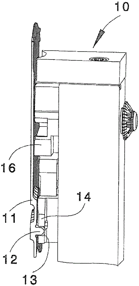
[0029] from in figure 2 In the side view of the cylinder cam section 10 in , it can be seen that the knitting needles 11 arranged parallel to one another in the grooves of the cylinder not shown in detail here have butts 12 which are in the needle control curve of the cam 14 13 to guide for controlling needle movement.

[0030] available through image 3 In the shape of the needle control curve identified in the detailed view of the triangle 14, the needle 11 performs the figure 1 Visible push-out and unwind movement. The cylinder cam, which is not shown in detail here, has a plurality of adjoining cylinder cam segments 10 of the same construction type, so that all needles of the syringe can be acted on in the same way by the cam 14 of the segment 10 . In the exemplary embodiment shown here, the cylinder cam section 10 is arranged radially ou...


PUM


Abstract

A knitting machine with longitudinally movably supported needles having a cam (14) with a needle control curve (13) for moving the needles, wherein the needle control curve (13) is at least Has an unwinding angle (α) of ≤ 35° in the tongue closure zone (Z).

Description

technical field [0001] The invention relates to a knitting or knitting machine (Wirkmaschine) with longitudinally displaceably mounted latch needles (Zungennadel) and with a cam (Schlossteil) with a needle control curve (Nadelsteuerkurve) for moving the needles . Background technique [0002] Such knitting machines are known, for example, from DE 2408924A1 and DE 3433290A1. These machines are also equipped with a sinker (Platine) that can move relative to the needle, so that the travel required for the bending of the pile is partly caused by the needle forming the pile and partly by the sinker associated with the needle. film passes. As a result, the needle control curve can have a flatter course than in machines in which the bending depth is determined solely by the needle movement. [0003] However, in this known machine with a latch needle, the needle control curve has a large steepness in the unwinding region (Abzugsbereich) of the needle (wherein the latch closure is...

Claims


Application Information

Patent Timeline
Patent Type & Authority Patents(China)
IPC IPC(8): D04B15/32
CPCD04B15/32D04B15/06D04B15/322D04B15/68
Inventor J-M.埃普勒
Owner SIPRA PATENTENTWICKLUNGS & BET GMBH (DE)
Learn More