Vacuum cover

A vacuum and cover technology, applied in the direction of drinking water vessels, etc., can solve the problems of high welding quality requirements, influence on heat preservation effect, and small friction force, etc., achieve low molding process requirements, avoid poor sealing performance, and improve heat preservation effect Effect

Active Publication Date: 2014-12-10
ZHEJIANG ENO HOUSEWARES
View PDF8 Cites 2 Cited by
  • Summary
  • Abstract
  • Description
  • Claims
  • Application Information

AI Technical Summary

Problems solved by technology

[0005] 1. The threaded body and the inner cover are connected by interference fit. When the cup cover is rotated for a long time, the friction between the threaded body and the inner cover will become smaller, and the threaded body will rotate relative to the inner cover, which will eventually lead to the inability to open the cup cover;
[0006] 2. The molding of the above-mentioned vacuum chamber is relatively complicated; in order to form the above-mentioned vacuum chamber, it is necessary to form a hollow cylindrical outer cover and an inner cover with a protrusion, and then weld the inner and outer covers to form a chamber. On the outer surface of the cup, it requires high welding quality, otherwise, on the one hand, the airtightness of the vacuum chamber cannot be guaranteed, and on the other hand, it will affect the appearance of the entire cup cover;
[0007] 3. Since the vacuum chamber extends from the protruding part to the outer cover, and the protruding part extends into the inside of the cup body, the heat will be transferred to the side walls of the inner cover and the outer cover along the side wall of the protruding part, and the heat preservation effect remains It needs to be improved. In addition, the vacuum cover is only provided with a sealing ring at the position that matches the inner wall of the cup to achieve a sealed connection. Poor sealing will inevitably affect the heat preservation effect. Therefore, the sealing effect of the vacuum cover also needs to be improved.

Method used


Image

  • Vacuum cover
  • Vacuum cover

Examples


Embodiment Construction

[0027] In the following, the present invention will be further described by using the following embodiments in conjunction with the accompanying drawings.

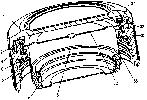
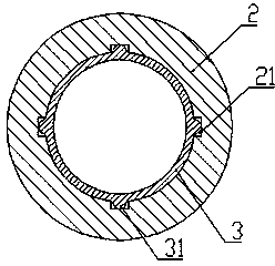
[0028] figure 1 It is a vacuum cover of the present invention, comprising a cover bottom 1, a cover body 2 fixedly connected with the cover bottom 1, the cover body 2 is made of heat insulating material, the inner side wall of the cover body 2 and the cup body The outer side wall of the cup is matched for detachable connection; and the vacuum liner 3 located inside the cover body 2 and the cover bottom 1, the vacuum liner 3 is inserted into the inner side of the cup body and is tightly connected with the cup body; The vacuum liner 3 is fixedly connected with the cover body 2 .

[0029] In the present invention, there is not only one way for the vacuum liner 3 to be fixedly connected to the cover body 2 , and methods such as threaded connection, bonding, and buckle connection can be selected. As a preference, this embodim...


PUM


Abstract

The invention discloses a vacuum cover, which comprises a cover bottom (1), a cover body (2) and a vacuum liner (3), wherein the cover body (2) is fixedly connected with the cover bottom (1) and is made of heat insulation materials, the inner side wall of the cover body (2) and the outer side wall of a cup body are matched to be detachably connected, the vacuum liner (3) is positioned inside the cover body (2) and the cover bottom (1) and is inserted into the inner side of the cup body to be connected with the cup body in a sealed way, and the vacuum liner (3) and the cover body (2) are fixedly connected. The vacuum cover solves the technical problems that the structure of the existing heat insulation cup cover is unreasonable, and in addition, the heat insulation effect is poor. The vacuum cover is particularly for a heat insulation cup with higher heat insulation effect.

Description

technical field [0001] The invention belongs to the field of design and manufacture of thermos cups, in particular to a vacuum cover on a thermos cup. Background technique [0002] Common thermos cups generally store heat through a vacuumized cup body to achieve heat preservation. However, if the heat preservation effect of the cup cover is not good, a large part of heat will be dissipated through the cup cover, which will affect the heat preservation effect of the overall thermos cup. Therefore, designing a cup cover with better thermal insulation effect becomes the key to ensure the thermal insulation effect of the thermos cup. [0003] Chinese patent document CN102641064A discloses a vacuum cup lid formed by laminating stainless steel material with injection molding material. Its inner lid 5, inner plug 6 and water sealing sheet 3 together form a chamber, and insulating material is inserted into the chamber to realize the cup lid. thermal insulation. However, due to th...

Claims


Application Information

Patent Timeline
Patent Type & Authority Patents(China)
IPC IPC(8): A47G19/22
Inventor 程金荣
Owner ZHEJIANG ENO HOUSEWARES
Why Eureka
Try Eureka