Rotating shaft clamping device

A shaft clamping and collet technology, which is applied in the direction of grinding workpiece brackets, etc., can solve the problems of easy slipping and rotation of the shaft, and achieve the effects of avoiding slipping or rotation, increasing friction, and ensuring stability

Inactive Publication Date: 2013-12-11
CHENGDU TIANYI NATURAL GAS COMPRESSOR MFG
View PDF0 Cites 2 Cited by
  • Summary
  • Abstract
  • Description
  • Claims
  • Application Information

AI Technical Summary

Problems solved by technology

[0004] The invention provides a compressor shaft grinding mechanism, which solves the problem that the shaft is easy to slip and rotate during grinding, so as to achieve the purpose of improving the grinding efficiency of the shaft

Method used


Image

  • Rotating shaft clamping device
  • Rotating shaft clamping device

Examples


Embodiment 1

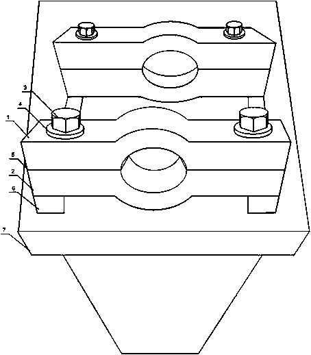
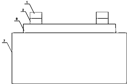
[0021] Such as figure 1 As shown, this embodiment includes a bracket 7, a slideway 6 and a fixing mechanism, the slideway 6 is installed on the bracket 7, the fixing mechanism includes an upper clamp 1 and a lower clamp 2, and the upper clamp 1 is slidably arranged on the slideway 6, the upper chuck 1 is provided with a semi-arc concave surface A, the lower chuck 2 is provided with a semi-arc concave surface B, the semi-arc concave surface A and the semi-arc concave surface B form a circular cavity, and the upper chuck 1 It is connected with the lower chuck 2 by bolts, and the inner surfaces of the semi-arc concave surface A and the semi-arc concave surface B are provided with anti-slip patterns. Adjust the bolt 3 between the upper chuck 1 and the lower chuck 2 so that the two ends of the rotating shaft are placed in the arc concave surface A, and then adjust the distance between the two by moving the two fixing mechanisms on the slide. The rotating shafts of different length...

Embodiment 2

[0024] Such as figure 1 As shown, on the basis of Embodiment 1, this embodiment also includes an elastic gasket 5 disposed between the upper chuck 1 and the lower chuck 2 . The upper chuck 1 and the lower chuck 2 will be close to each other when they are fixed, and the force generated by the grinding machine when it contacts the rotating shaft will make the upper chuck 1, lower chuck 2 and the end of the rotating shaft collide with each other, and there will be a shock on the rotating shaft. Certain damage; the elastic gasket 5 provided can protect the end of the rotating shaft, reduce the impact force on the end of the rotating shaft, and prevent it from being damaged.

Embodiment 3

[0026] Such as figure 1 As shown, in this embodiment, on the basis of Embodiment 1, the bottom of the lower chuck 1 is also symmetrically provided with two anti-vibration feet, which can buffer most of the force, avoid the vibration of the fixing mechanism during grinding, and ensure the smoothness of grinding. Accuracy; there is a ring gasket 4 between the bolt 3 and the upper chuck 1. Since the position of the rotating shaft needs to be adjusted from time to time during grinding, the adjustment of the bolt 3 is relatively frequent, and long-term use will damage the bolt 3. If the thread is detached or the head of the bolt 3 is separated from the screw rod, the ring gasket 4 provided can strengthen the connection between the bolt 3 and the upper chuck 1, so as to extend the service life of the bolt 3 .


PUM


Abstract

The invention discloses a rotating shaft clamping device which comprises a support, a sliding way and a fixing mechanism. The sliding way is installed on the support, the fixing mechanism comprises an upper clamping head and a lower clamping head, the upper clamping head is arranged on the sliding way in a sliding mode, a semicircle concave surface A is arranged on the upper clamping head, a semicircle concave surface B is arranged on the lower clamping head, a circular cavity is formed by the semicircle concave surface A and the semicircle concave surface B, the upper clamping head is connected with the lower clamping head through bolts, and anti-sliding patterns are arranged on the inner surface of the semicircle concave surface A and the inner surface of the semicircle concave surface B. After a rotating shaft is fixed in a manual mode, a contact part of the circular cavity and the end portion of the rotating shaft has the relative movement trend when polishing is started, the anti-sliding patterns are arranged on the inner surface of the semicircle concave surface A and the inner surface of the semicircle concave surface B, therefore, the friction force between the circular cavity and the end portion of the rotating shaft can be increased, sliding or followed rotating of the rotating shaft in the circular cavity is avoided, and the stability of polishing machining is guaranteed.

Description

technical field [0001] The invention relates to a natural gas compressor, in particular to a rotating shaft clamping device. Background technique [0002] There are many types of natural gas compressors, including piston compressors. The main advantages of piston compressors are: a wide range of applicable pressure, can be used for low pressure (including vacuum), medium pressure, high pressure and ultra-high pressure; high efficiency, its high efficiency Compared with rotary compressors and speed compressors, the adiabatic efficiency of large piston compressors is above 80%; it has strong adaptability, a wide range of displacement, and can maintain high efficiency even at a small displacement , and the exhaust volume is slightly affected by the fluctuation of the exhaust pressure, and the impact of the gas density on the performance of the compressor is not significant, so the machine has good versatility. [0003] In the production process of natural gas compressors in mo...

Claims


Application Information

Patent Timeline
Patent Type & Authority Applications(China)
IPC IPC(8): B24B41/06
Inventor 孙伟余世春
Owner CHENGDU TIANYI NATURAL GAS COMPRESSOR MFG
Why Eureka
Try Eureka