Horizontally-moving device

A technology of translation device and moving track, which is applied in the direction of transportation, packaging, conveyors, etc., can solve the problems of high power source power, low precision, waste of travel, etc., and achieve the effect of lengthening the travel of translation

Active Publication Date: 2013-12-11
精诚工科汽车系统有限公司
View PDF10 Cites 11 Cited by
  • Summary
  • Abstract
  • Description
  • Claims
  • Application Information

AI Technical Summary

Problems solved by technology

At present, most of the translation devices adopt non-cantilever structure, which greatly limits the route of the object when it moves to the position to be translated or moves from the position to other positions.
Although some translation devices adopt the cantilever structure, most of them are single-stage extension, and the distance of the cantilever extension is too small, while a few multi-stage extension cantilevers are composed of chains and other structures, which have poor stability and low precision.
In order to realize the symmetry of the left and right sides, the existing translation device relies on increasing the length of the overall equipment. On the one hand, it takes up a lot of space and causes a waste of travel. Without position adjustment function, it is difficult to achieve left and right symmetry
The existing translation device does not have the ability to lift the object to be moved. When the workpiece needs to be lifted, this problem is often solved by adding special equipment for lifting the object, which takes up a lot of space and the cost of the equipment is high.
In the process of translation, it is necessary to overcome the large sliding friction force, which requires a large power source, and the friction is easy to cause damage to the parts, and the service life of the equipment is short

Method used


Image

  • Horizontally-moving device
  • Horizontally-moving device
  • Horizontally-moving device

Examples


Embodiment Construction

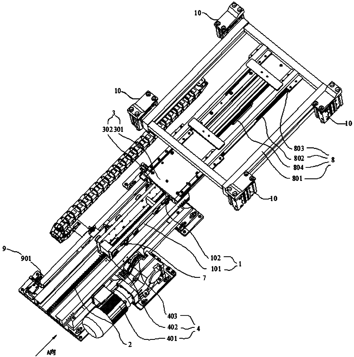
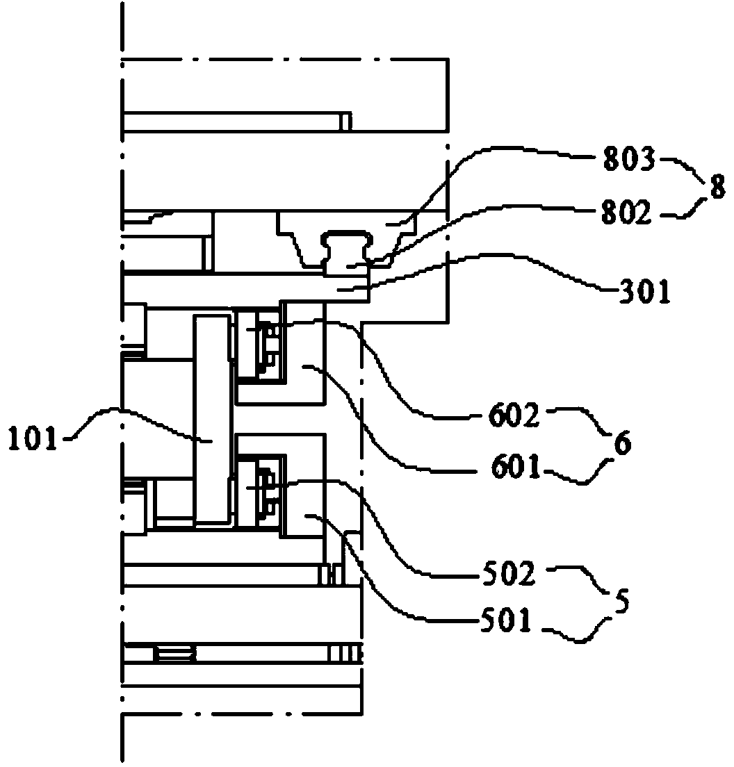
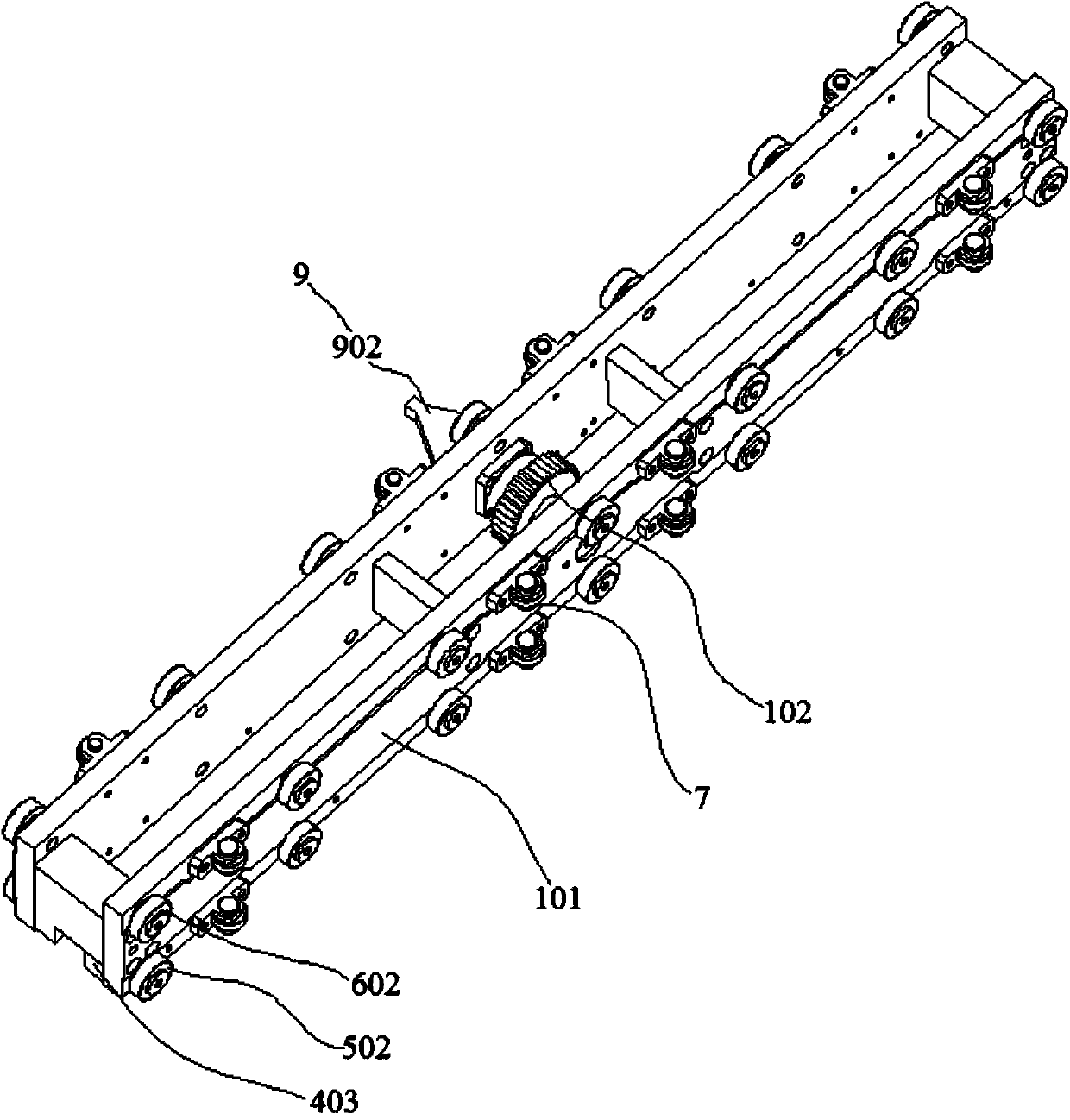
[0020] The translation device of the embodiment of the present invention will be described in detail below with reference to the accompanying drawings.

[0021] In describing the present invention, it is to be understood that the terms "center", "upper", "lower", "front", "rear", "left", "right", "vertical", "horizontal", The orientations or positional relationships indicated by "top", "bottom", "inner", "outer", etc. are based on the orientations or positional relationships shown in the drawings, and are only for the convenience of describing the present invention and simplifying the description, rather than indicating or implying References to components or elements must have a particular orientation, be constructed, and operate in a particular orientation and therefore should not be construed as limiting the invention.

[0022] The terms "first" and "second" are used for descriptive purposes only, and cannot be understood as indicating or implying relative importance or imp...


PUM


Abstract

The invention discloses a horizontally-moving device and relates to the field of horizontally-moving devices. Under the condition that the length of the horizontally-moving device is not increased, the horizontally-moving distance is lengthened. A horizontally-moving lifting device comprises a fixed rack, a first-level horizontally-moving assembly, a multiplier horizontally-moving assembly and a first driving assembly. The fixed rack is fixedly arranged in the first direction; the first-level horizontally-moving assembly comprises a first-level horizontally-moving support, the first-level horizontally-moving support can conduct linear motion in the first direction, a rotary idler gear is further arranged on the first-level horizontally-moving support, and the idler gear is meshed with the fixed rack; the multiplier horizontally-moving assembly comprises a multiplier horizontally-moving support and a multiplier horizontally-moving rack, the multiplier horizontally-moving rack is arranged in the first direction and is meshed with the idler gear, and the multiplier horizontally-moving support is arranged on the multiplier horizontally-moving rack; the first driving assembly can drive the first-level horizontally-moving support to conduct linear motion in the first direction. The horizontally-moving device is used for horizontally moving a workpiece.

Description

technical field [0001] The invention relates to the field of translation devices, in particular to a translation device. Background technique [0002] Translating devices are suitable for various occasions where workpieces are moved from one side to the other. At present, most translation devices adopt a non-cantilever structure, which greatly limits the route of the object moving to the position to be translated or from the position to other positions. Although some translation devices adopt a cantilever structure, most of them are single-stage extension, and the distance of the cantilever extension is too small, while a few multi-stage extension cantilevers are composed of chains and other structures, which have poor stability and low precision. In order to realize the symmetry of the left and right sides, the existing translation device relies on increasing the length of the overall equipment. On the one hand, it takes up a lot of space and causes a waste of travel. Wit...

Claims


Application Information

Patent Timeline
IPC IPC(8): B65G25/02
Inventor 王秋虎郝建军孟树杰李建和尚永昌孔卫华张志锟淮旭迪王阳赵军郭江
Owner 精诚工科汽车系统有限公司
Why Eureka
Try Eureka