Concrete wood formwork steel buckle

A wood formwork steel buckle and concrete technology, which is applied to the joints of formwork/formwork/work frame, the preparation of building components on site, construction, etc., which can solve the problems of formwork splitting, difficulty in installing or disassembling formwork, waste, etc. question

Inactive Publication Date: 2013-12-11
于光成
View PDF6 Cites 5 Cited by
  • Summary
  • Abstract
  • Description
  • Claims
  • Application Information

AI Technical Summary

Problems solved by technology

[0002] At present, iron nails are used to assemble concrete wood formwork in building construction, which has high technical requirements and low efficiency, and it is difficult to install or disassemble the formwork, which can easily cause the formwork to split; the installation method is single, and if it is to adapt to various construction environments, it is necessary It takes time and effort to remove the iron nails and reassemble the formwork; moreover, the iron nails cannot be reused, resulting in waste; when assembling the solid wood formwork, the iron nails can easily cause the formwork to split along the wood grain

Method used


Image

  • Concrete wood formwork steel buckle
  • Concrete wood formwork steel buckle
  • Concrete wood formwork steel buckle

Examples


Embodiment 1

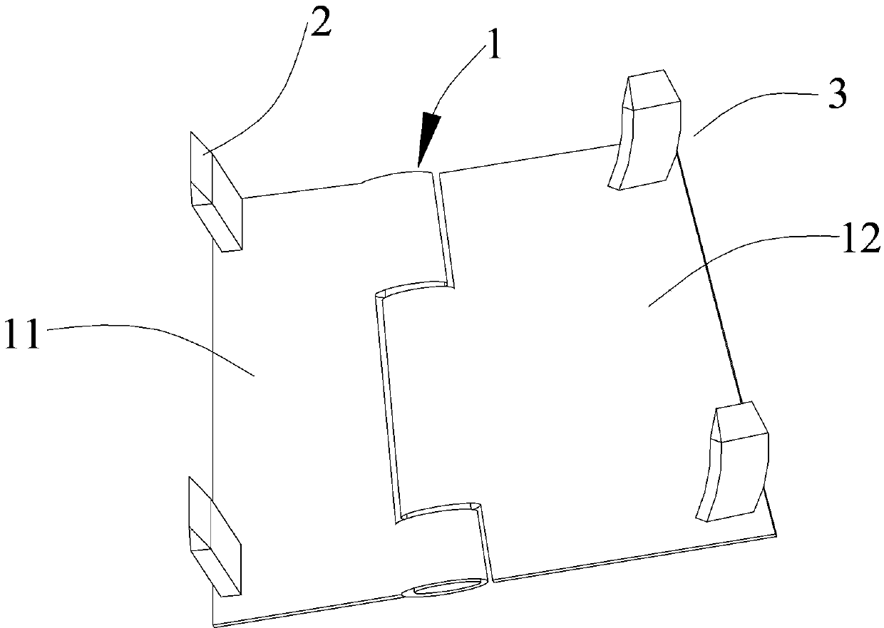
[0015] Such as figure 1 As shown, the concrete wooden mold steel buckle includes a hinge 1. The hinge 1 is composed of a left leaf 11 and a right leaf 12 hinged by pins. There is a positioning claw 2 on the two corners of the left leaf 11 away from the pins. , the positioning nail claw 2 is a straight claw, and the positioning nail claw 2 is a flat chisel shape, and there is a turning nail claw 3 on the two corners of the right sheet 12 away from the pin, and the described steering nail claw 3 is a flat chisel shape, The steering nail claw 3 is a curved claw, and the steering nail claw 3 is bent to the left, and the bending angle is 15° o .

Embodiment 2

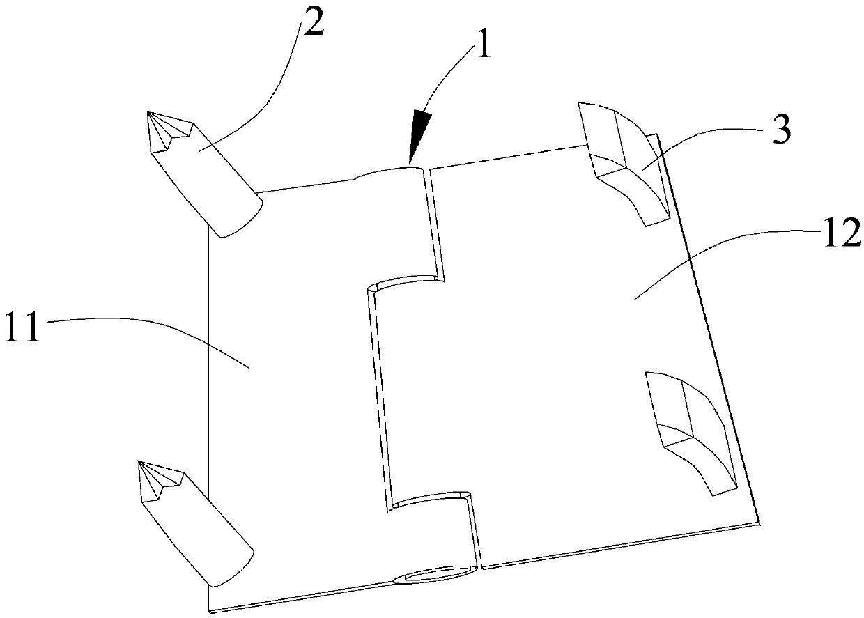
[0017] Such as figure 2 As shown, the concrete wooden mold steel buckle includes a hinge 1. The hinge 1 is composed of a left leaf 11 and a right leaf 12 hinged by pins. There is a positioning claw 2 on the two corners of the left leaf 11 away from the pins. , the positioning nail claw 2 is a straight claw, the positioning nail claw 2 is nail-shaped, and there is a steering nail claw 3 on the two corners of the right sheet 12 away from the pin, and the steering nail claw 3 is a flat chisel shape, so The steering nail claw 3 is a curved claw, and the steering nail claw 3 is bent to the left, and the bending angle is 12° o .

Embodiment 3

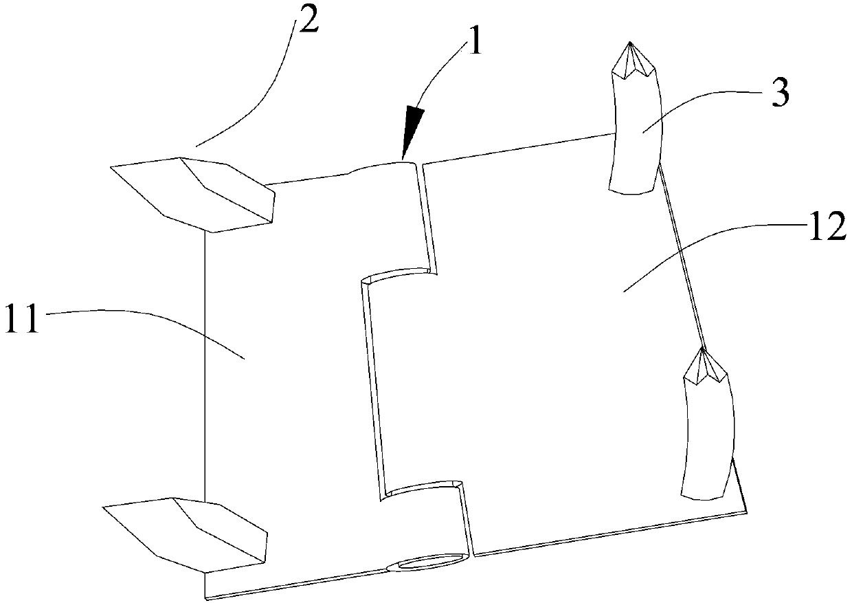
[0019] Such as image 3 As shown, the concrete wooden mold steel buckle includes a hinge 1. The hinge 1 is composed of a left leaf 11 and a right leaf 12 hinged by pins. There is a positioning claw 2 on the two corners of the left leaf 11 away from the pins. , the positioning nail claw 2 is a straight claw, and the positioning nail claw 2 is a flat chisel shape, and there is a steering nail claw 3 on the two corners of the right sheet 12 away from the pin, and the steering nail claw 3 is nail-shaped, so The steering nail claw 3 is a curved claw, and the steering nail claw 3 is bent to the left, and the bending angle is 16° o .


PUM

PropertyMeasurementUnit
Bending angleaaaaaaaaaa

Abstract

The invention provides a concrete wood formwork steel buckle which comprises a hinge, and the hinge is formed by a left hinge leaf and a right hinge leaf through a pin in a hinged mode. Positioning pin claws are arranged on the two corners, far away from the pin, of the left hinge leaf respectively, and turning pin claws are arranged on the two corners, far away from the pin, of the right hinge leaf. The turning function of the hinge is used for assembling or disassembling concrete wood formworks, the concrete wood formwork steel buckle is easy to operate, capable of being used for assembling inner and outer formworks, also capable of being used for other purposes of a construction site and easy to disassemble after use, the formworks and the steel buckle are not prone to being damaged, the steel buckle can be recycled, and waste is reduced.

Description

technical field [0001] The invention belongs to the field of building construction equipment, in particular to a concrete wood formwork steel buckle used for splicing concrete wood formwork for building construction. Background technique [0002] At present, iron nails are used to assemble concrete wood formwork in building construction, which has high technical requirements and low efficiency, and it is difficult to install or disassemble the formwork, which can easily cause the formwork to split; the installation method is single, and if it is to adapt to various construction environments, it is necessary It is time-consuming and labor-intensive to remove the iron nails and reassemble the formwork; moreover, the iron nails cannot be reused, resulting in waste; when the solid wood formwork is assembled, the iron nails are also easy to split the formwork along the wood grain. Contents of the invention [0003] The technical problem to be solved by the present invention is ...

Claims


Application Information

Patent Timeline
IPC IPC(8): E04G17/02
Inventor 于光成
Owner 于光成
Why Eureka
Try Eureka