Cable connector assembly with improved shielding member

a shielding member and cable connector technology, applied in the direction of coupling device connection, coupling protective earth/shielding arrangement, electrical equipment, etc., can solve the problems of weak combination between the mounting portion and the collaborating portion, and the cable connector assembly cannot work normally

Inactive Publication Date: 2011-04-12
HON HAI PRECISION IND CO LTD
View PDF7 Cites 18 Cited by
  • Summary
  • Abstract
  • Description
  • Claims
  • Application Information

AI Technical Summary

Benefits of technology

[0008]Accordingly, an object of the present invention is to provide a cable connector assembly having an improved shielding member to position a printed circuit board and prevent from splitting thereof.

Problems solved by technology

An electrical connector is connected with a cable or more cables to form a cable connector assembly, and the connector always connected with the cable by a printed circuit board, contacts of the connector and a connecting portion of the cable are soldered on the printed circuit board, as the printed circuit board is received in a shielding member unsteadily, so the contacts will be unstable on the printed circuit board as the cable be rocky, so that the cable connector assembly can't work normally.
However, the combination between the mounting portions and the collaborating portions may be weak to induce the first shielding member to be separated from the second shielding member.

Method used


Image

  • Cable connector assembly with improved shielding member
  • Cable connector assembly with improved shielding member
  • Cable connector assembly with improved shielding member

Examples


Embodiment Construction

[0019]Reference will now be made to the drawing figures to describe the present invention in detail.

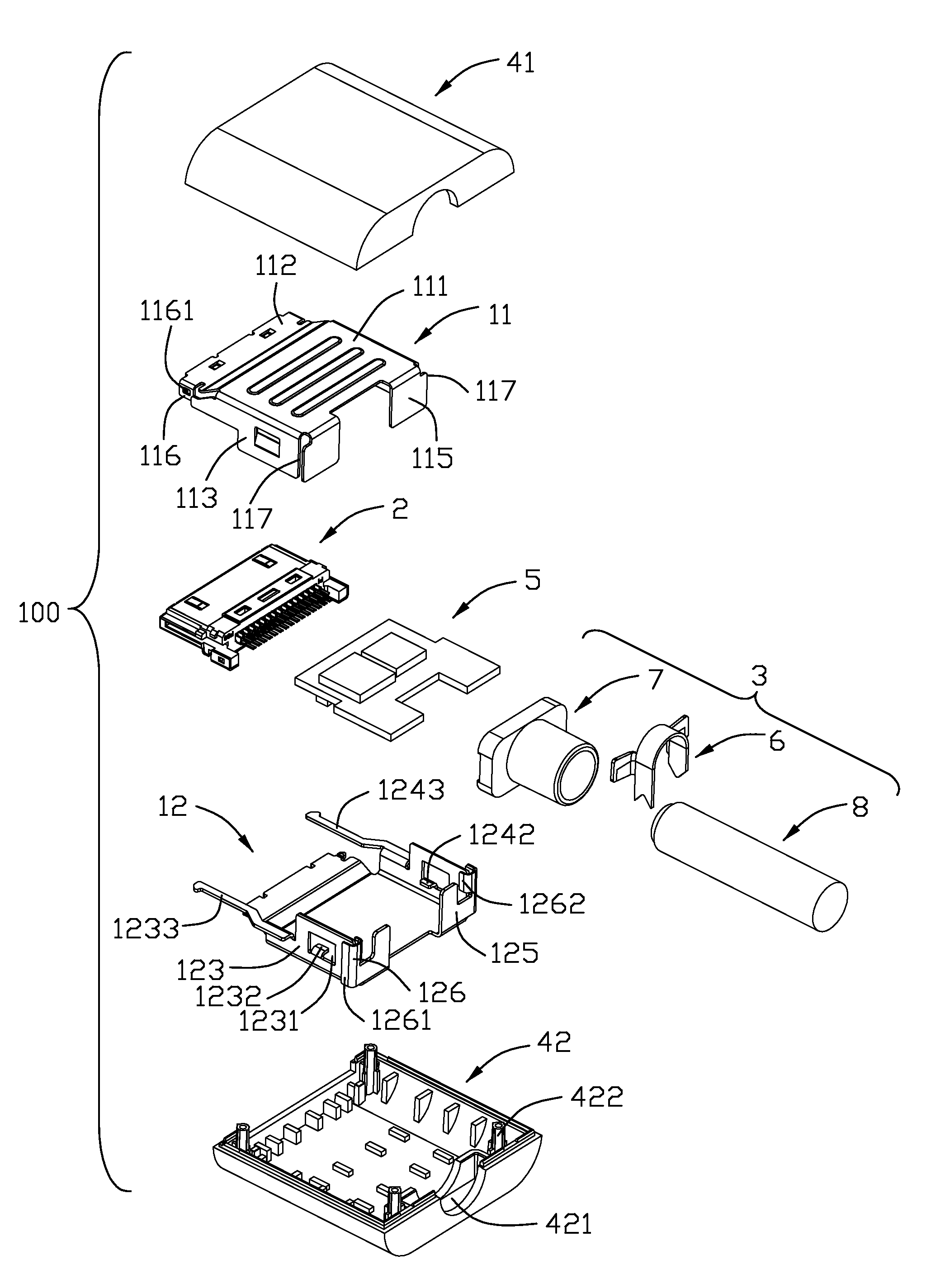
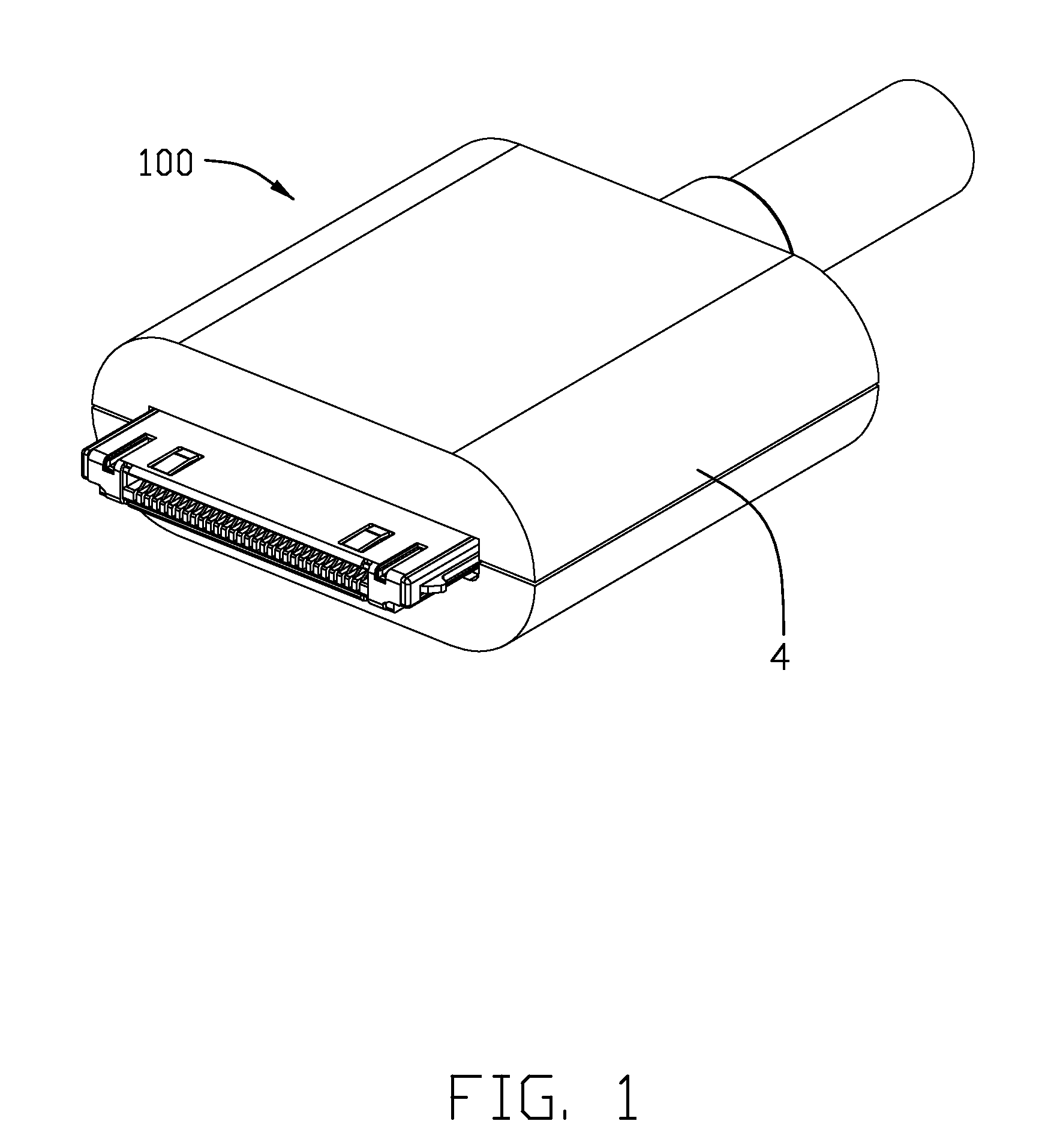
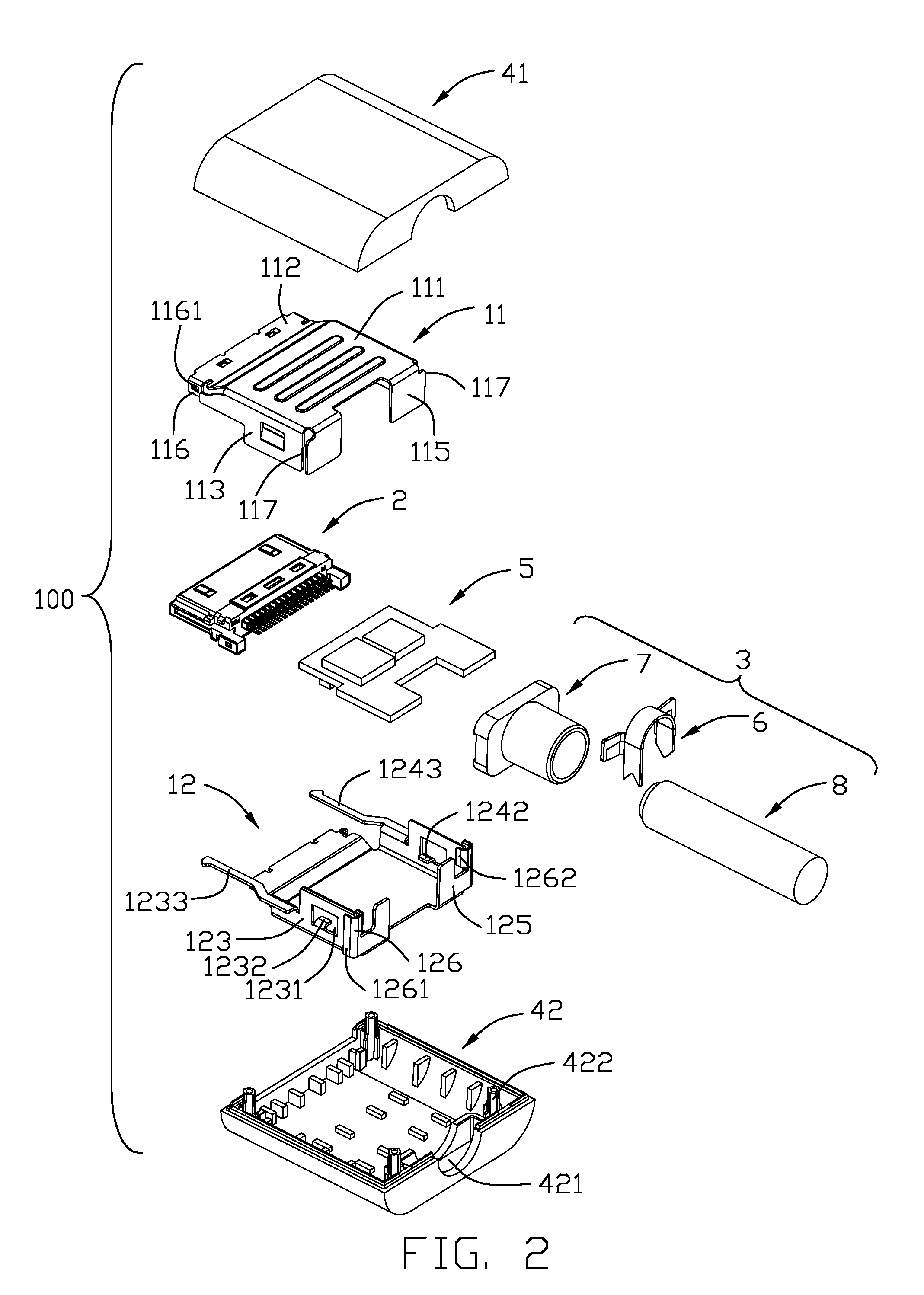
[0020]Referring to FIGS. 1-8, a cable connector assembly 100 in accordance with the present invention comprises an upper shielding member 11, a lower shielding member 12 together with the upper shielding member 11 to form a receiving space 10, a connector 2 mating with a complementary connector, a printed circuit board 5 electrically connected with the connector 2 and accommodated in the receiving space 10, an insulated cover 4 and a cable assembly 3. The connector 2 comprises a metallic shell 21 and an insulative housing 22 with a group of first contacts 23 and a group of second contacts 24 retained therein.

[0021]Referring to FIGS. 2-3 and FIG. 6, the upper shielding member 11 is made of metallic material and includes a base portion 111, a mounting portion 112 extending forwards from a front end of the base portion 111, a pair of side walls 113, 114 extending downwards from lateral s...


PUM


Abstract

A cable connector assembly (100) includes an insulative housing (22) having a plurality of contacts received therein, a cable assembly (3) connected with the contacts by a printed circuit board (5), an upper shielding member (11) and a lower shielding member (12) together with the upper shielding member to form a receiving space (10). Each of the upper shielding member and the lower shielding member have a base portion (111, 121) and a plurality of vertical walls (113, 114, 115, 123, 124, 125) extending from the base portion. The lower shielding member (12) defines a stopping portion (126) to prevent the upper shielding member (11) from moving along a transverse direction. The stopping portion (126) is of U-shaped and comprises a first restricting flake (1261) and a second restricting flake (1262), and a corresponding vertical wall (113) of the upper shielding member is located between the first restricting flake (1261) and the second restricting flake (1262).

Description

BACKGROUND OF THE INVENTION[0001]1. Field of the Invention[0002]This application claims priority to prior Chinese patent applications 200820302424.3 and 200820302764.6, the disclosure of which are incorporated herein by reference.[0003]The present invention generally relates to a cable connector assembly, and more particularly to a cable connector assembly with an improved shielding member.[0004]2. Description of Related Art[0005]An electrical connector is connected with a cable or more cables to form a cable connector assembly, and the connector always connected with the cable by a printed circuit board, contacts of the connector and a connecting portion of the cable are soldered on the printed circuit board, as the printed circuit board is received in a shielding member unsteadily, so the contacts will be unstable on the printed circuit board as the cable be rocky, so that the cable connector assembly can't work normally.[0006]In addition, CN patent No. 101232136A issued to Shen o...

Claims


Application Information

Patent Timeline
Patent Type & Authority Patents(United States)
IPC IPC(8): H01R13/648
CPCH01R13/6583H01R13/6593H01R13/6658H01R13/506H01R13/6275H01R13/6594
Inventor ZHANG, XIAO-KANGSHI, HOU-YUKO, DAVID
Owner HON HAI PRECISION IND CO LTD
Why Eureka
Try Eureka