Automatic hole forming equipment and hole forming method for composite airfoil components

A composite material and automatic manufacturing technology, which is applied in the direction of drilling/drilling equipment, boring/drilling, metal processing equipment, etc., can solve the problems that cannot meet the needs of composite airfoil parts.

Active Publication Date: 2014-04-16
SHENYANG AIRCRAFT CORP
View PDF5 Cites 15 Cited by
  • Summary
  • Abstract
  • Description
  • Claims
  • Application Information

AI Technical Summary

Problems solved by technology

Although the conventional five-coordinate automatic hole-making method has the functions of five-axis linkage, normal adjustment, and hole-making

Method used


Image

  • Automatic hole forming equipment and hole forming method for composite airfoil components
  • Automatic hole forming equipment and hole forming method for composite airfoil components
  • Automatic hole forming equipment and hole forming method for composite airfoil components

Examples


Embodiment Construction

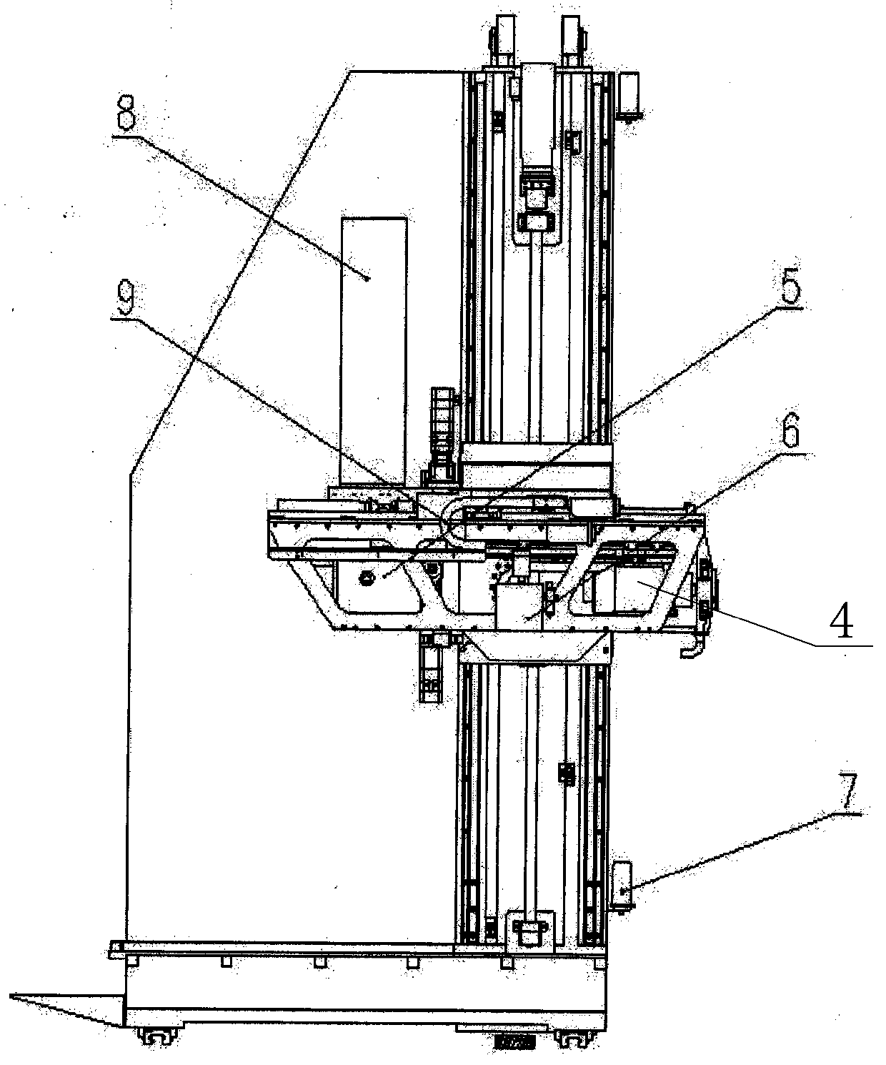
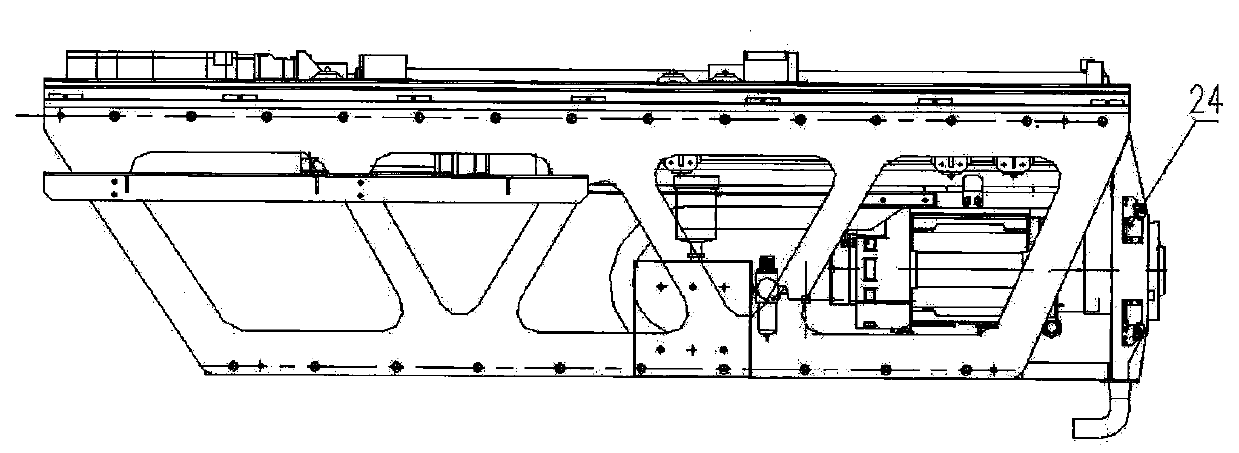
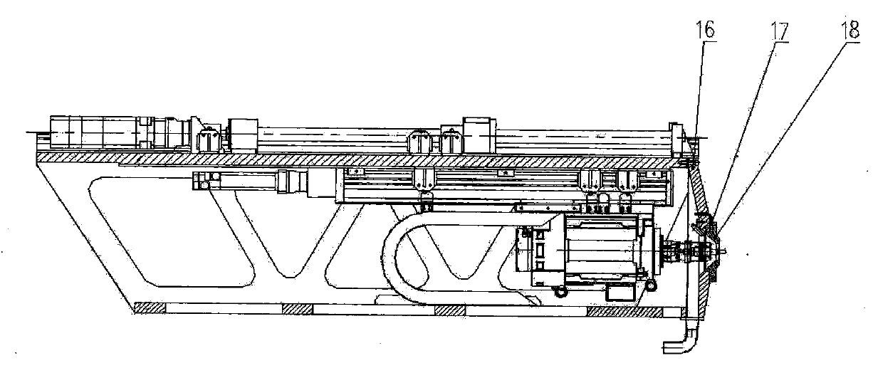
[0047] Such as Figure 1 to Figure 4 As shown, an automatic hole-making equipment for composite airfoil parts is a five-axis linkage numerical control equipment, including main frame 1, B-axis bracket 2, A-axis turntable 3, Z-axis part 4, and Y-axis drag chain 8. Z-axis drag chain 9, chip suction device 5, tool lubrication system 6 and lubricating system oil pump 7, the Z-axis part 4 is equipped with a main shaft, and the main shaft is hydraulically clamped with an integrated structure of drilling, reaming and spot facing The composite cutting tool of the Z-axis part; four laser distance measuring sensors 24 are arranged symmetrically at the end of the Z-axis part 4, and are distributed in four quadrants; A pressure foot 18 is arranged on the circumference of the central hole, and a pressure foot sensor 17 is arranged on the pressure foot 18 .

[0048] The method for making holes by using the above-mentioned automatic hole making equipment for airfoil parts of composite mater...


PUM


Abstract

The invention relates to automatic hole forming equipment for composite airfoil components. The automatic hole forming equipment is five-axis linkage numerically controlled equipment, and comprises a main rack, a B-axis support, an A-axis rotary table, a Z-axis subassembly, a Y-axis drag chain, a Z-axis drag chain, a scrap suction device, a knife lubricating system and an oil pump of the lubricating system, wherein a spindle is arranged on the Z-axis subassembly; a component knife which can be used for drilling holes, reaming holes and reaming pits is hydraulically clamped on the spindle; four laser distance measuring sensors are symmetrically arranged at ends of the Z-axis subassembly and are distributed on four quadrants; a pressure foot support is arranged below the Z-axis subassembly; and pressure feet are arranged on the periphery of a center hole of the pressure foot support, and are provided with pressure foot sensors. By using the automatic hole forming equipment and the hole forming method, the clamping and positioning precision is high, the accuracy of formed holes is high, and damage to composites in a hole forming process is reduced, so that the quality of a product is improved while the work efficiency is improved.

Description

technical field [0001] The invention relates to an automatic hole-making device and a method thereof for airfoil components of composite materials, and is provided with a fully automatic numerical control machining method. Background technique [0002] After the 1990s, the aviation manufacturing industry put forward high-quality, high-efficiency, low-cost production requirements for aircraft assembly technology that can adapt to a variety of products. As an effective way to improve assembly efficiency and assembly quality, the automatic hole-making method is increasingly in demand and development trend. Although the conventional five-coordinate automatic hole-making method has the functions of five-axis linkage, normal adjustment, and hole-making accuracy detection, it still cannot meet the requirements of large-size, variable-thickness, and complex interlayer composite airfoil parts. need. Improve the automatic hole making process to reduce the splitting and delamination ...

Claims


Application Information

Patent Timeline
IPC IPC(8): B23B39/24
CPCB26F1/16
Inventor 欧阳黄晓宇刘哲
Owner SHENYANG AIRCRAFT CORP
Why Eureka
Try Eureka