A packer structure

A technology of packer and seat seal, which is applied in sealing/isolation, wellbore/well components, earthwork drilling and production, etc. It can solve the problems of inability to achieve effective isolation, large radial design space, and small gap in the annulus of isolation To achieve the effect of ensuring the stimulation effect, improving the cementing quality and increasing the radial thickness

Active Publication Date: 2016-09-28
BC P INC CHINA NAT PETROLEUM CORP +1
View PDF10 Cites 0 Cited by
  • Summary
  • Abstract
  • Description
  • Claims
  • Application Information

AI Technical Summary

Problems solved by technology

[0005] The compression packer compresses the rubber tube by axial pressure, the rubber tube becomes thicker in the radial direction, fills the annulus gap, and realizes isolation. Small, when the rubber tube is thin and the annular gap is large, effective isolation is often not achieved
The expandable packer achieves isolation by injecting fluid into the rubber tube to radially expand the rubber tube to fill the annulus gap. The packer has a complex structure and high manufacturing costs
[0006] In summary, the compression packer in the prior art has the disadvantages of large radial design space and small annulus sealing gap, and the expansion packer has the disadvantages of complex structure and high cost

Method used


Image

  • A packer structure

Examples


Embodiment 1

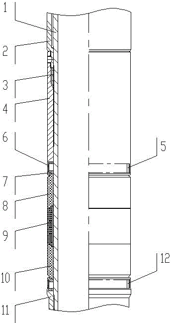
[0029] A packer structure, including a central pipe 1, a seat seal cylinder 2, a rubber cylinder seat and a rubber cylinder, the rubber cylinder seat includes an upper rubber cylinder seat 4 and a lower rubber cylinder seat 11, the seat seal cylinder 2, the upper rubber cylinder The seat 4, the rubber tube and the lower rubber tube seat 11 are set on the central tube 1 from top to bottom in sequence. A self-locking mechanism is provided between the seat sealing tube 2 and the upper rubber tube seat 4. Expansion valves are respectively provided at both ends of the rubber tube. open institutions.

[0030] The preferred implementation mode of this embodiment is that the rubber cylinder includes an upper rubber cylinder 8, a middle rubber cylinder 9 and a lower rubber cylinder 10, and the upper rubber cylinder 8, the middle rubber cylinder 9 and the lower rubber cylinder 10 are combined to form a rubber cylinder. When the cylinder 8 , the middle rubber cylinder 9 and the lower rub...

Embodiment 2

[0038] A packer structure mainly includes a center pipe 1, a seat seal cylinder 2, a rubber cartridge seat, a rubber cartridge, an end ring 7, an expansion ring, and the like. The rubber tube is placed on the lower cylindrical surface of the central tube 1, and the two ends of the rubber tube are provided with end rings 7 and expansion rings. The lower rubber tube seat 11 is connected to the lower end of the central tube 1 through threads, and the upper rubber tube seat 4 is placed on the central tube. 1. On the upper part of the rubber cylinder, the rubber cylinder seat 4 is threadedly connected with the seat seal cylinder 2, and a stop ring 3 is arranged between the seat seal cylinder 2 and the rubber cylinder seat 4.

[0039] The rubber cylinder includes an upper rubber cylinder 8, a middle rubber cylinder 9 and a lower rubber cylinder 10, and the upper rubber cylinder 8 and the middle rubber cylinder 9, the middle rubber cylinder 9 and the lower rubber cylinder 10 cooperate...


PUM


Abstract

The invention discloses a packer structure. The packer structure comprises a central tube, a setting barrel, a rubber barrel seat and a rubber barrel, wherein the rubber barrel seat comprises an upper rubber barrel seat and a lower rubber barrel seat; the setting barrel, the upper rubber barrel seat, the rubber barrel and the lower rubber barrel seat are orderly sleeved on the central tube from top to bottom, a self-locking mechanism is arranged between the setting barrel and the upper rubber barrel seat, and two ends of the rubber barrel are respectively provided with an end ring and an expansion ring in order. The packer structure disclosed by the invention is not only small in radial gap, but also capable of effectively packing the great annular gap; meanwhile, the price is low, the well cementation quality is improved, and capacity increasing and revamp are guaranteed.

Description

technical field [0001] The invention relates to a packer structure, which is used for oil and gas well cementing and production stimulation transformation operations for oil and gas development, and belongs to the technical field of downhole tool manufacturing for oil and gas field operations. Background technique [0002] In the cementing construction of oil and gas wells, packers are often used to prevent oil, gas, water, etc. from channeling, effectively achieve permanent mechanical isolation of the annulus, and improve cementing quality. [0003] In the process of oil and gas well stimulation and stimulation, packers are often used to achieve interlayer isolation and jamming, to ensure the pertinence of well completion and stimulation, and to maximize the effect of stimulation and stimulation. [0004] At present, the traditional packer structures used in oil and gas well cementing and stimulation operations mainly include compression type and expansion type. For exampl...

Claims


Application Information

Patent Timeline
Patent Type & Authority Patents(China)
IPC IPC(8): E21B33/122
Inventor 唐欣刘运楼李斌石磊张毅超伍军
Owner BC P INC CHINA NAT PETROLEUM CORP
Why Eureka
Try Eureka