A strain gauge sticking mechanism

A technology of strain gauges and blades, which is applied in the field of automatic pasting mechanism, can solve the problems of low precision and poor quality of manual pasting, and achieve the effects of improving quality, solving low position precision, and increasing precision

Active Publication Date: 2015-12-09
NORTHWESTERN POLYTECHNICAL UNIV
View PDF6 Cites 0 Cited by
  • Summary
  • Abstract
  • Description
  • Claims
  • Application Information

AI Technical Summary

Problems solved by technology

[0003] In order to overcome the shortcomings of poor quality and low precision of manual patching, the present invention aims to design a strain gauge sticking mechanism that can suck up the positioned strain gauge and send it to the hole of the elastic body and automatically paste it in the middle position.

Method used


Image

  • A strain gauge sticking mechanism
  • A strain gauge sticking mechanism
  • A strain gauge sticking mechanism

Examples


Embodiment Construction

[0013] The technical solutions of the present invention will be further described below in conjunction with specific implementation examples.

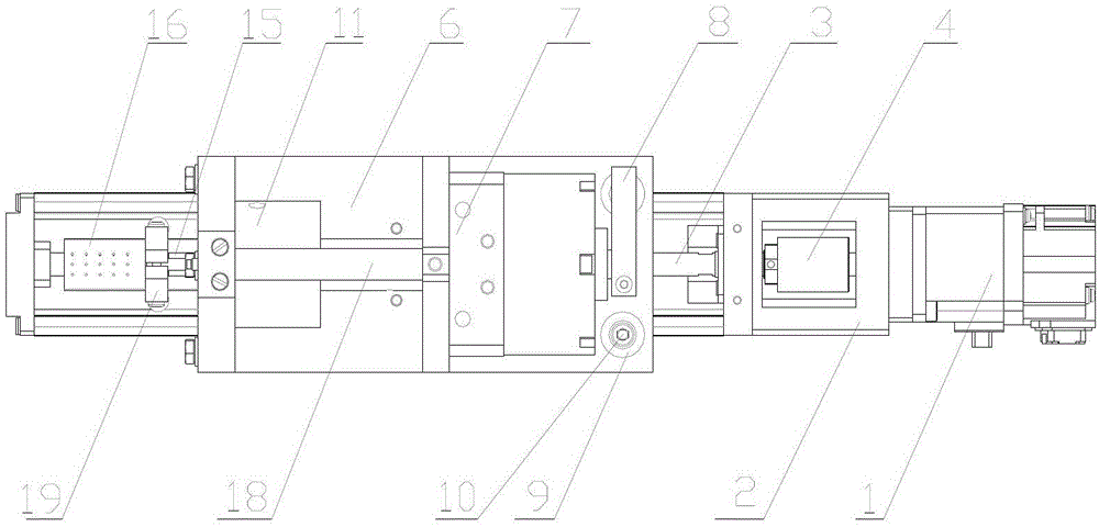
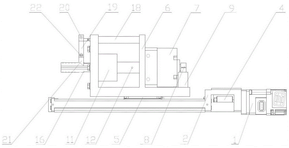
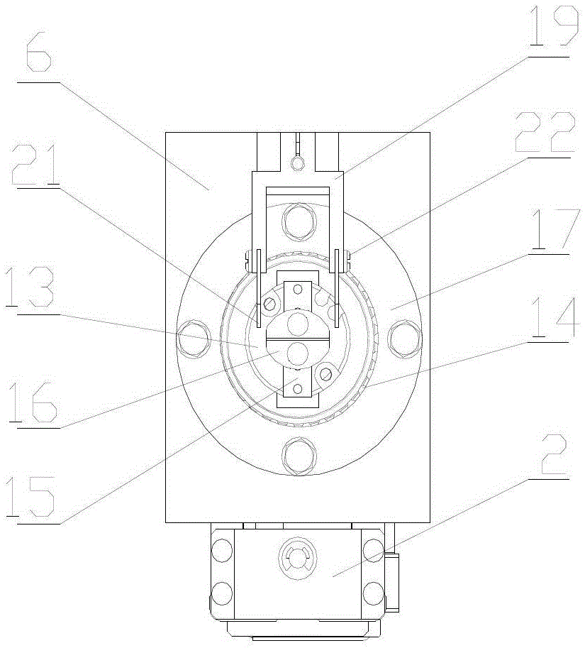
[0014] refer to Figure 1~3 , the present invention includes a servo motor 1, a linear guide rail 2, a lead screw 3, a coupling 4, a slider 5, an F-type motion base 6, a turning cylinder 7, a limit block 8, a limit column 9, an adjustment screw 10, Support sleeve 11, connecting screw 12, air claw 13, bearing 14, L-shaped bracket 15, sticking head 16, bearing end cover 17, telescopic cylinder 18, knife rest 19, knife rest tightening screw 20, blade 21 and blade tightening screw twenty two.

[0015] The linear guide rail 2 in the present invention is fixed on the horizontal workbench, the servo motor 1 is fixed on the linear guide rail 2, the servo motor 1 is connected with the lead screw 3 through the shaft coupling 4, and the slider 5 can be used on the linear guide rail 2 as a For linear motion in the direction, the distance and dir...


PUM


Abstract

The invention relates to a strain gauge pasting mechanism, in particular to a strain gauge pasting mechanism which can achieve automatic pasting of hole internal strain gauges. The strain gauge pasting mechanism solves the problems that due to the fact that common elastomer hole internal strain gauge pasting is completed mainly through manual work, accuracy and quality are low. According to the technical scheme, the strain gauge pasting mechanism is novel and mainly comprises a servo motor, a linear guide rail, a lead screw, a slider, an F-shaped motion base, an overturn air cylinder, pneumatic claws, pasting heads, a telescopic air cylinder, a tool rest and a blade. The linear motion combination of the servo motor, the lead screw and the linear guide rail is adopted, and therefore accuracy control over strain gauge hole internal pasting depth is achieved. Vertical opening-and-closing motion is achieved through the two arc-shaped pasting heads, and therefore strain gauges can be firmly pasted in elastomer holes. Two strain gauges can be pasted in the holes at a time through 180-degree rotation of the overturn air cylinder. The strain gauge pasting mechanism achieves automatic pasting of the hole internal strain gauges, greatly improves accuracy, and improves quality.

Description

technical field [0001] The invention relates to a strain gauge pasting mechanism, in particular to an automatic pasting mechanism for strain gauges in elastic body holes. Background technique [0002] In order to accurately measure the deformation of the elastic body, a common method is to paste a strain gauge on the surface of the elastic body, and indirectly measure the deformation of the elastic body by measuring the deformation of the strain gauge. At present, the automatic bonding of strain gauges to elastic bodies is mainly carried out when the surface of the elastic body is flat, while the bonding of strain gauges in the holes of general elastic bodies is mainly done manually. The position accuracy of manual pasting is low, the quality is poor, and the strain gauge cannot be pasted accurately in the required position in the hole of the elastic body. Contents of the invention [0003] In order to overcome the shortcomings of poor quality and low precision of artific...

Claims


Application Information

Patent Timeline
Patent Type & Authority Patents(China)
IPC IPC(8): F16B11/00
Inventor 钟靖李树军秦现生谭小群袁顺龙武俊强胡鹏张洋任瑞敏白晶杨雪保
Owner NORTHWESTERN POLYTECHNICAL UNIV
Why Eureka
Try Eureka