
Method and device used for state monitoring and fault diagnosis of relay

A fault diagnosis and relay technology, applied in the electrical field, to achieve the effect of predicting hidden dangers of faults and avoiding maintenance

Active Publication Date: 2013-12-11
北京昊鹏智能技术有限公司
View PDF9 Cites 23 Cited by
  • Summary
  • Abstract
  • Description
  • Claims
  • Application Information

AI Technical Summary

Problems solved by technology

[0006] In view of the shortcomings of existing relay fault state monitoring and fault diagnosis methods and devices

Method used


Image

  • Method and device used for state monitoring and fault diagnosis of relay
  • Method and device used for state monitoring and fault diagnosis of relay
  • Method and device used for state monitoring and fault diagnosis of relay

Examples


Embodiment Construction

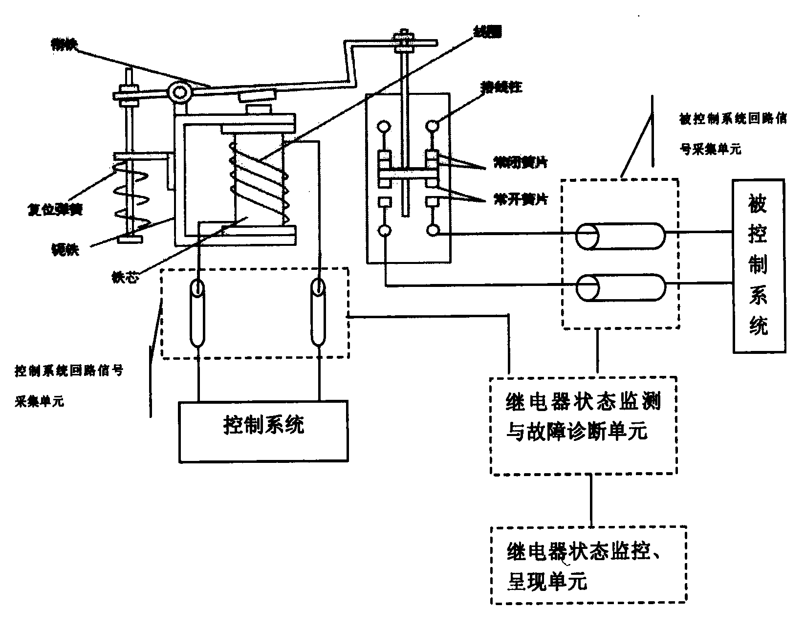
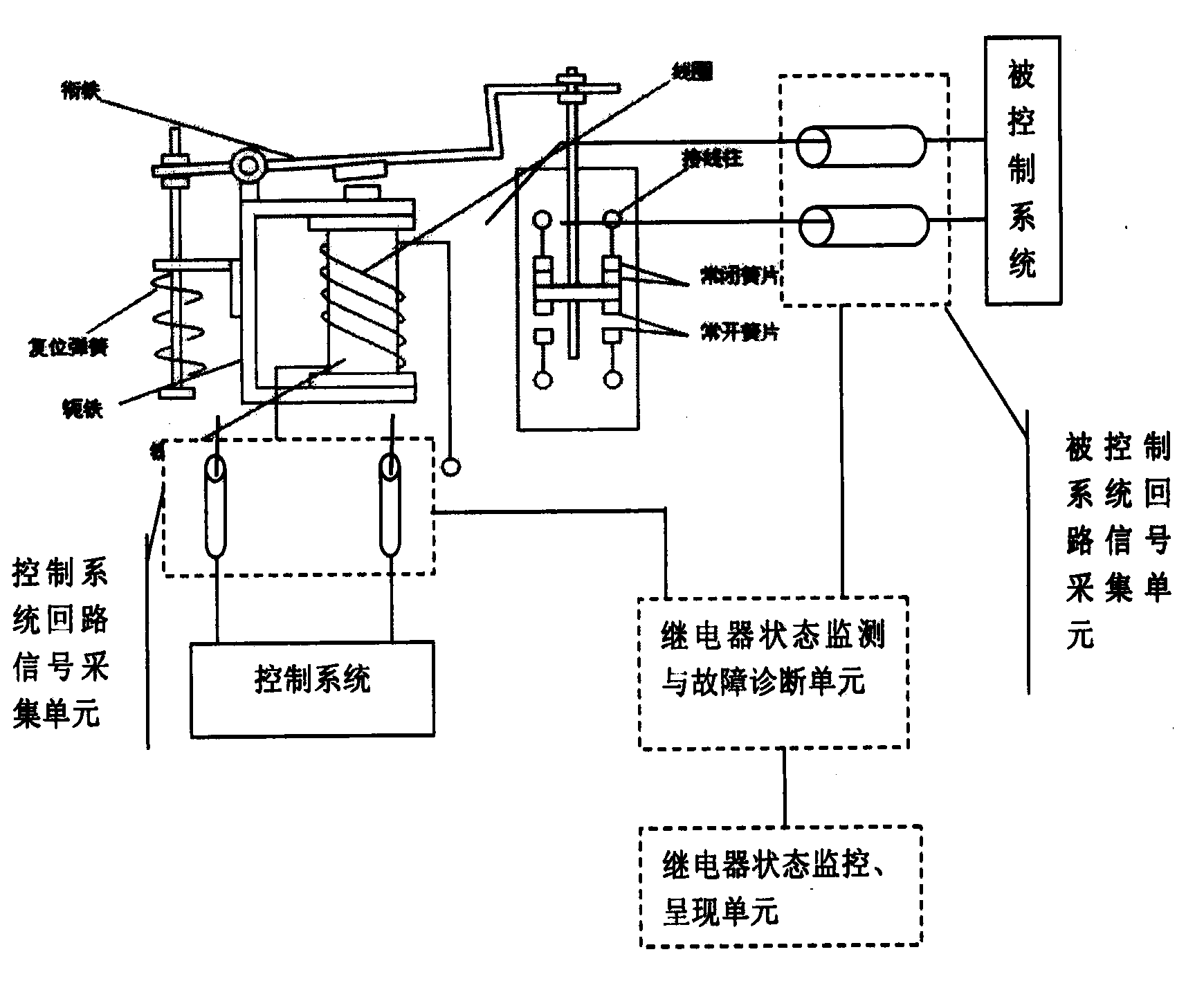
[0026] The following describes the embodiment of the present invention in detail by taking an electromagnetic relay as an example.

[0027] Electromagnetic relays are mainly composed of coils, iron cores, armatures, yokes, return springs and two or more sets of reeds.

[0028] There are two connection methods for the controlled system circuit of the electromagnetic induction relay. one is as image 3 As shown, the controlled system circuit is connected to the normally open terminal of the relay, and the other is as shown in Figure 4 As shown, the controlled system circuit is connected to the normally closed terminal terminal of the relay, and the working principles of the two connections are just opposite. The electromagnetic relay uses the principle of electromagnetic induction to work: when a certain voltage is applied to both ends of the control system loop coil, a current will flow through the coil, thereby producing an electromagnetic effect, and the armature will o...


PUM


Abstract

The invention provides a method and device used for achieving state monitoring and fault diagnosis of a relay through monitoring and analyzing the change of a control system circuit and a controlled system circuit of the relay. According to the method used for state monitoring and fault diagnosis of the relay, a selected fault sample is processed by means of a mode recognition algorithm, a classifier used for state diagnosis of the relay is obtained, the discrimination function of each class is obtained, and a result of state monitoring and fault diagnosis and repairing and maintenance suggestions are provided for relevant workers. The method and device used for state monitoring and fault diagnosis of the relay of the relay have the advantages that defects of an existing relay detection technique are overcome, the timing sequence of turning on and turning off of the relay does not need to be learned, hidden danger of a fault can be predicated, and then the relay can be maintained in advance to avoid the fault.

Description

technical field [0001] The invention relates to the field of electricity, in particular to a method and a device for monitoring and diagnosing the state of a relay by monitoring and analyzing changes in a relay control system loop and a controlled system loop. Background technique [0002] The relay is an electric control device, which is an electrical appliance that causes the controlled quantity to undergo a predetermined step change in the electrical output circuit when the change of the input quantity (excitation quantity) meets the specified requirements. It has the interactive relationship between the control system loop (also known as the input loop) and the controlled system loop (also known as the output loop). It is usually used in automatic control circuits. It is actually an "automatic switch" that uses small currents to control large currents. It plays the role of automatic adjustment, safety protection, and conversion circuits in the circuit. Widely used in ...

Claims


Application Information

Patent Timeline
Patent Type & Authority Applications(China)
IPC IPC(8): G01R31/327
Inventor 李雅婧
Owner 北京昊鹏智能技术有限公司
Learn More