
Interactive electronic demonstration system

An electronic demonstration and interactive technology, applied in the multimedia field, can solve the problem of high cost and achieve the effect of low cost

Active Publication Date: 2013-12-11
NANJING MAGEWELL ELECTRONICS CO LTD
View PDF1 Cites 34 Cited by
  • Summary
  • Abstract
  • Description
  • Claims
  • Application Information

AI Technical Summary

Problems solved by technology

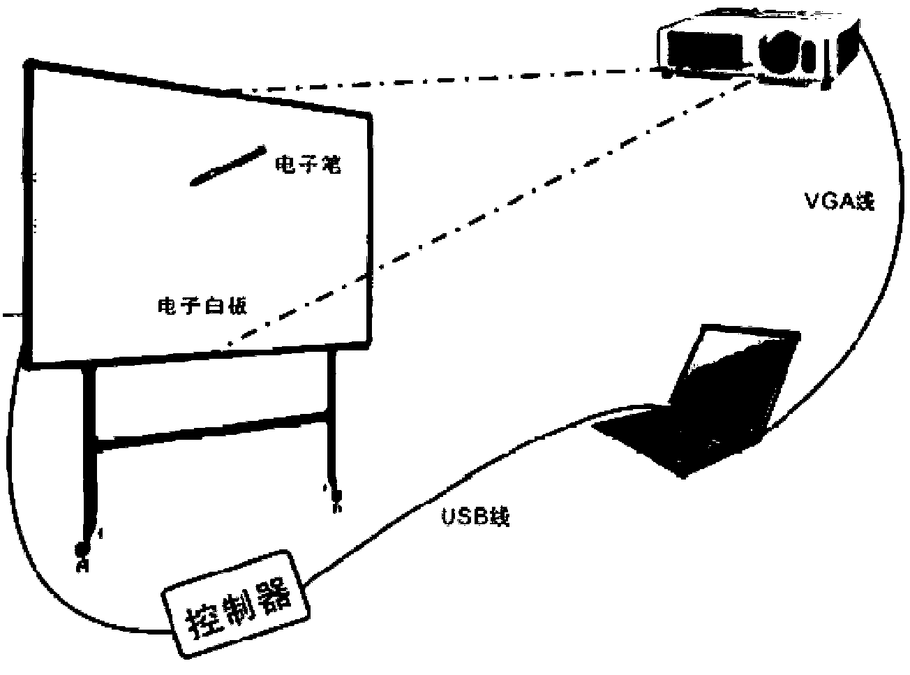
However, the users of this system still have to perform demonstration and interactive operations in front of the interactive projection screen. The system is a closed structure, and special equipment is required, and the cost is relatively high.

Method used


Image

  • Interactive electronic demonstration system
  • Interactive electronic demonstration system
  • Interactive electronic demonstration system

Examples


Embodiment 1

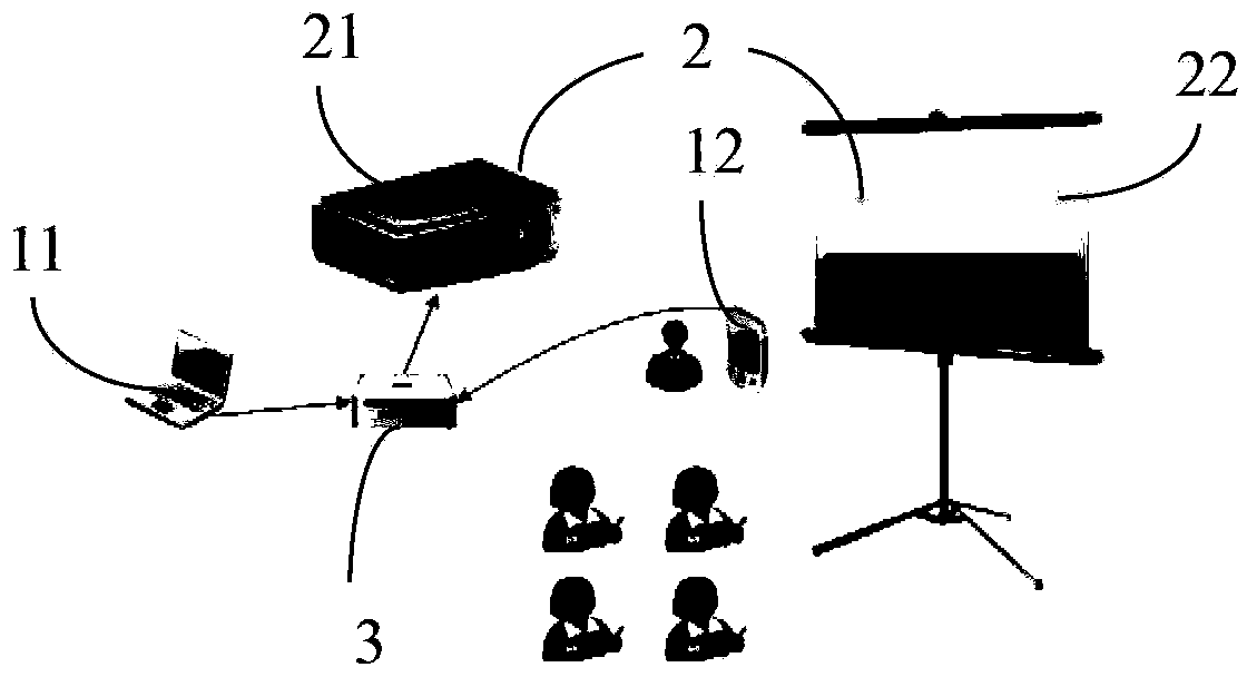
[0063] Such as figure 2 As shown, an interactive electronic demonstration system includes:

[0064] An operation terminal 1, used for storing and demonstrating display content and performing demonstration operations;

[0065] Display terminal 2, used to display the display content of the operation terminal;

[0066] An interactive controller 3 is used to obtain the display content and operation information of the operation terminal 1 and send them to the display;

[0067] The video input interface of the interactive controller 3 is connected with the video output interface of the operation terminal 1 by wire or wirelessly, and the video output interface of the interactive controller 3 is connected with the video input interfaces of the operation terminal 1 and the display terminal 2 by wire or wirelessly.

[0068] In this embodiment, the operation terminal 1 is composed of a notebook computer 11 and a tablet computer 12 , and the display terminal 2 is composed of a projecto...

Embodiment 2

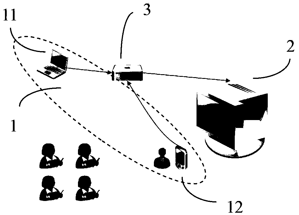
[0074] The difference between this embodiment and Embodiment 1 is that the display terminal 2 is a large-screen computer, such as image 3 shown.

Embodiment 3

[0076] Such as image 3 As shown in the interactive electronic demonstration system, the interactive controller 3 is equipped with interactive control software, the display terminal 2 is also used for demonstration operations, and the interactive controller 3 is also used to identify the operation actions of the display terminal and simulate mouse or keyboard operation signals Returning to the notebook computer 11, the notebook computer 11 makes a corresponding response according to the operation signal. Demonstration steps such as Figure 5 Shown:

[0077] The computer image of step 1 notebook computer 11 is transmitted to interactive controller 3;

[0078] Step 2 The interactive controller 3 transmits the image to the large electronic screen 23 for the audience to watch the demonstration;

[0079] Step 3 Simultaneously, the interactive controller 3 transmits the image to the tablet computer 12 in a wireless manner;

[0080] Step 4 The presenter uses the tablet computer 1...


PUM


Abstract

An interactive electronic demonstration system comprises an operating terminal, a display terminal and an interaction controller; the operating terminal is used for storing and demonstrating displayed contents and performing demonstration operation; the display terminal is used for displaying the displayed contents of the operating terminal; the interaction controller is used for obtaining and transmitting the displayed contents and operating information of the operating terminal to the display terminal; the video input interface of the interaction controller is connected with the video output interface of the operating terminal through a wire or wirelessly, and the video output interface of the interaction controller is connected with the video input interfaces of the display terminal and the operating terminal through wires or wirelessly. The operating terminal can be a desktop computer, a laptop computer, a tablet personal computer or a mobile phone. The operating terminal can be connected into the system through the wire or wirelessly, various conventional intelligent terminals with the computer function can be adopted at the operating terminal, and a user can perform demonstration interaction operation in an entire area.

Description

technical field [0001] The invention relates to the field of multimedia technology, in particular to an interactive electronic demonstration system. Background technique [0002] The traditional interactive electronic demonstration system consists of a desktop computer, a projector and a wired connection to an interactive projection screen. The interactive projection screen can be an electronic whiteboard and a large display operation screen. Demonstrate interactive operations in front of the screen, such as figure 1 shown. [0003] Chinese patent CN202677683 discloses an interactive electronic teaching system, the system includes a host computer 1, an electromagnetic induction handwriting input display 2 for displaying the display content of the host computer and controlling the host computer 1, and a display screen 2 for projecting the display content of the host computer The interactive projector 3 that feeds back the operation information, the projection screen 4 that ...

Claims


Application Information

Patent Timeline
Patent Type & Authority Applications(China)
IPC IPC(8): G06F3/14
Inventor 韩莉马飞
Owner NANJING MAGEWELL ELECTRONICS CO LTD
Learn More