Capacitive coupling device and filter

A technology of capacitive coupling and connection position, which is applied in the field of communication, can solve the problems that the second harmonic is close to the passband of the filter and the influence of out-of-band suppression

Pending Publication Date: 2020-10-20
武汉凡谷陶瓷材料有限公司
View PDF2 Cites 3 Cited by
  • Summary
  • Abstract
  • Description
  • Claims
  • Application Information

AI Technical Summary

Problems solved by technology

[0004] There is also a negative coupling hole in the form of a through hole or a blind hole between the two resonators to realize the negative coupling between the two resonators. The second harmonic caused by this form of negative coupling is far from the passband of the filter. near, out-of-band suppression has some influence

Method used


Image

  • Capacitive coupling device and filter
  • Capacitive coupling device and filter
  • Capacitive coupling device and filter

Examples


Embodiment 1

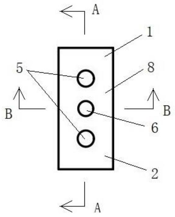
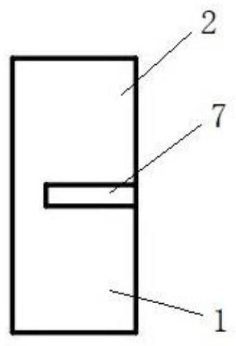
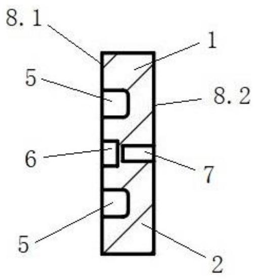
[0059] Such as Figure 1-5 As shown, this embodiment provides a capacitive coupling device, including a first dielectric resonator 1 and a second dielectric resonator 2 connected to each other, and the body surfaces of the first dielectric resonator 1 and the second dielectric resonator 2 8 are provided with a tuning hole 5, the tuning hole 5 is a blind hole, the surface of the first dielectric resonator 1 and the second dielectric resonator 2 are provided with a conductive layer, the first dielectric resonator 1 and the second dielectric resonator Negative coupling holes are provided between the resonators 2, and the negative coupling holes include longitudinal blind holes 6 and transverse blind grooves 7, the longitudinal blind holes 6 are cylindrical, that is, the cross section is circular; the transverse blind grooves are square grooves, and the transverse blind grooves The width of the blind groove 7 is smaller than the diameter of the longitudinal blind hole 6, the lengt...

Embodiment 2

[0061] Such as Figure 6-8 As shown, this embodiment provides a capacitive coupling device, which is basically similar in structure to the coupling device in Embodiment 1, the difference is that in this embodiment, the transverse blind groove 7 is located on the body surface 8 where the two dielectric resonators are connected. Where the front side 8.1 meets the body side 9, the width and length of the transverse blind groove 7 are greater than the diameter of the longitudinal blind hole 6, and the top of the longitudinal blind hole 6 runs through the bottom surface of the transverse blind groove and communicates with the transverse blind groove 7 .

Embodiment 3

[0063] Such as Figure 9-13 As shown, this embodiment provides a capacitive coupling device, including a first dielectric resonator 1, a second dielectric resonator 2, a third dielectric resonator 3 and a fourth dielectric resonator 4 connected to each other, the first dielectric resonator Positive coupling with a certain amount of coupling is generated between the device 1, the second dielectric resonator 2, the third dielectric resonator 3 and the fourth dielectric resonator 4 through the T-shaped coupling hole 10 provided in the center, and the first dielectric resonator 1. The body surfaces 8 of the second dielectric resonator 2, the third dielectric resonator 3 and the fourth dielectric resonator 4 are all provided with tuning holes 5, and the tuning holes 5 are blind holes. The third dielectric resonator 3 and the fourth dielectric resonator The body surface 8 of the resonator 4 is provided with input and output ports, and the end face of the input and output ports 11 is...


PUM


Abstract

The invention discloses a capacitive coupling device and a filter. The device at least comprises a first dielectric resonator and a second dielectric resonator, a negative coupling hole is formed between the first dielectric resonator and the second dielectric resonator; the negative coupling hole comprises a longitudinal blind hole and a transverse blind groove, the longitudinal blind hole is located in the surface of a body at the connection position of the first dielectric resonator and the second dielectric resonator and is perpendicular to the surface of the body, and the transverse blindgroove is located in the body at the connection position of the first dielectric resonator and the second dielectric resonator. According to the capacitive coupling device, the longitudinal blind hole and the transverse blind groove are formed between the two dielectric resonators to form the negative coupling hole, the negative coupling between the two dielectric resonators is achieved, and thestructure is simple; the structure is used in the filter, because the area formed by two holes is larger, a transmission zero point can be formed at the low end of the passband of the filter, the rectangular coefficient of the filter is increased, the performance of the filter is improved, and the size of the filter is reduced.

Description

technical field [0001] The invention belongs to the technical field of communication, and in particular relates to a capacitive coupling device and a filter. Background technique [0002] In the field of communication, with the development of technology, the performance requirements of filters in the system are getting higher and higher. With the improvement of requirements, the high-power microwave filter at the base station has the characteristics of high index, small size and low cost. When realizing these high-performance filters, limited by the size of the cavity, the filters need to be realized using new materials or technologies. [0003] Limited by the material characteristics of the dielectric filter, it is generally necessary to add a transmission zero point when designing the filter. Dielectric filters are more difficult to achieve capacitive cross-coupling than metal filters. Among the existing designs, Patent No. 201310688407.3 discloses three possible soluti...

Claims


Application Information

Patent Timeline
Patent Type & Authority Applications(China)
IPC IPC(8): H01P1/208H01P7/10
CPCH01P1/208H01P7/10
Inventor 刘文钟伟刚朱晖
Owner 武汉凡谷陶瓷材料有限公司
Why Eureka
Try Eureka