Termite Monitoring and Attraction Devices

A technology of termites and traction ropes, which is applied to the device for catching or killing insects, application, animal husbandry, etc., can solve the problems of complex structure of termite monitoring devices, and achieve the effect of simple structure, simple layout and convenient use

Inactive Publication Date: 2014-10-29
龚仲君
View PDF12 Cites 0 Cited by
  • Summary
  • Abstract
  • Description
  • Claims
  • Application Information

AI Technical Summary

Problems solved by technology

[0004] The invention provides a termite monitoring and luring device to solve the problem of complex structure of the existing termite monitoring device

Method used


Image

  • Termite Monitoring and Attraction Devices
  • Termite Monitoring and Attraction Devices
  • Termite Monitoring and Attraction Devices

Examples


Embodiment 1

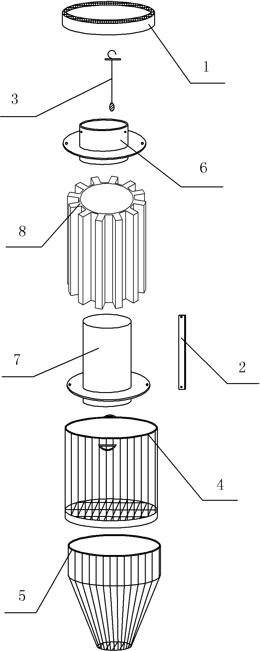
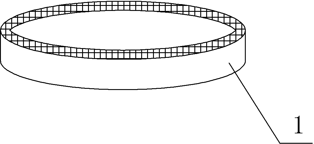
[0028] A termite monitoring and luring device in this embodiment, such as figure 1 As shown, it includes a cover 1, a traction rope 3, an upper cylinder 6, a sleeve 8, a lower cylinder 7, an induction strip 2, a housing body 4 and a base 5, and the cover 1, the housing body 4 and the base 5 constitute In the shell of this embodiment, the traction rope 3, the upper cylinder 6, the sleeve 8, the lower cylinder 7 and the induction strip 2 are arranged in the housing main body 4, and the sleeve 8 and the induction strip 2 are located on the upper cylinder 6 and the lower cylinder. Between the bodies 7, the upper end of the traction rope 3 passes through the upper cylinder 6 and hangs on the induction bar 2.

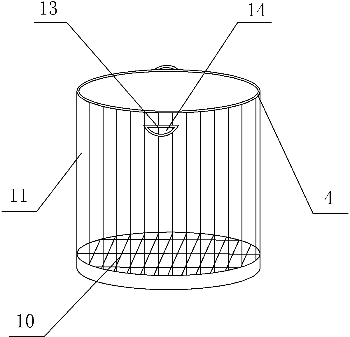
[0029] Such as image 3 As shown, the housing main body 4 is cylindrical, and the channel 11 is formed by several vertical spacers. Ear 13 has a jack 14 on the fixed ear. Such as Figure 4 As shown, there is a drainage hole 51 on the base 5, and the base 5 is a hollowed-o...

Embodiment 2

[0034] The lure 81 in the first embodiment is replaced with a booby-killer. The difference between the lure 81 and the booby-killer is that the lure 81 only contains an attractant, while the booby-killer not only contains an attractant but also a poison. When it is found or known that there are termites in areas such as building construction, rivers, reservoir dams, etc., it is only necessary to replace the sleeve 8 with lure core 81 in Embodiment 1 with the sleeve 8 of trap core to trap and kill termites, which is very convenient , to achieve a multi-purpose.


PUM


Abstract

The invention discloses a termite monitoring, luring and killing device, which comprises a shell and an inner core which is arranged in the shell. A cover body and a through hole for termites to enter and exit are arranged on the shell. The cover body is a transparent cover. The inner core comprises a hollow cylinder, a sleeve which is sheathed on the cylinder, a luring strip and a pulling rope. A luring core is longitudinally arranged on the sleeve. Two clamping rings are arranged on the cylinder. The sleeve is arranged between the two clamping rings. The distance between the two clamping rings is matched with the length of the sleeve. Installation holes for containing the luring strip are correspondingly formed in the two clamping rings. The luring strip is fixedly arranged on the clamping rings through the installation holes. A connecting hole is formed in the top end of the luring strip. A fixing hole is formed in the bottom end of the luring strip. A hook is arranged at one end of the pulling rope. A tin pendant is arranged at the other end of the pulling rope. A warning belt is additionally arranged on the pulling rope. The hook is connected with the connecting hole. The pulling rope crosses the cylinder and the tin pendant on the pulling rope freely sags into the hollow part of the cylinder. A threading hole which is matched with the section of the pulling rope is formed in the cylinder. The length of the pulling rope is smaller than the distance from the threading hole to the bottom end of the cylinder.

Description

technical field [0001] The invention belongs to the technical field of pest traps. Background technique [0002] Termites are pests that seriously endanger production and life. They not only harm crops and trees, but also have a great destructive ability to house buildings, rivers, and reservoir dams, and even cause sudden collapse of houses and collapse of embankments. Therefore, it is very necessary to discover the existence of termites in the above-mentioned areas in time and to kill the termites in the above-mentioned areas. [0003] The invention patent with the application number "201210395039" discloses an electronic monitoring system for monitoring termite damage through radio frequency identification, including a central processing unit, at least one electronic tag embedded in the monitoring area for monitoring termite damage, and an electronic tag capable of receiving Portable radio frequency identification equipment for signals, the electronic tag is connected wi...

Claims


Application Information

Patent Timeline
Patent Type & Authority Patents(China)
IPC IPC(8): A01M1/02A01M1/20
Inventor 龚仲君
Owner 龚仲君
Why Eureka
Try Eureka