Supercharge Your Innovation With Domain-Expert AI Agents!

Cemented carbide roller ring groove milling cutter fixture

A technology of cemented carbide and groove milling cutter, which is applied in clamping, manufacturing tools, metal processing equipment and other directions, can solve the problem of waste of cemented carbide roller ring groove milling cutter, etc., and achieves improved machining accuracy, low cost and simple structure Effect

Active Publication Date: 2015-08-05
ZHEJIANG HENGCHENG CEMENTED CARBIDE CO LTD
View PDF8 Cites 0 Cited by
  • Summary
  • Abstract
  • Description
  • Claims
  • Application Information

AI Technical Summary

Problems solved by technology

[0003] The invention provides a cemented carbide roller ring groove milling cutter fixture, which aims to solve the problem of serious waste of cemented carbide roller ring groove cutters in the prior art

Method used


Image

  • Cemented carbide roller ring groove milling cutter fixture
  • Cemented carbide roller ring groove milling cutter fixture
  • Cemented carbide roller ring groove milling cutter fixture

Examples


Embodiment Construction

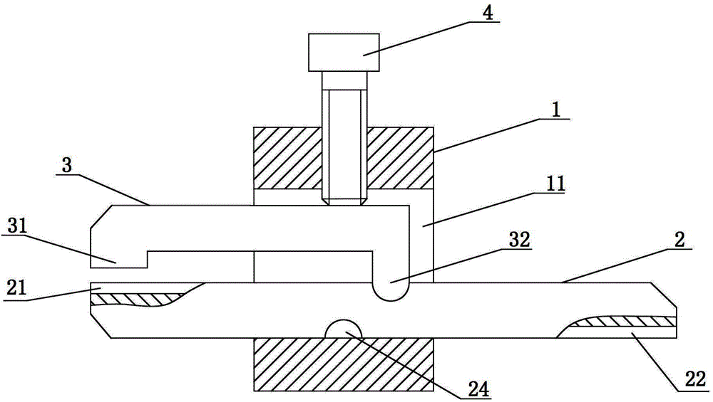
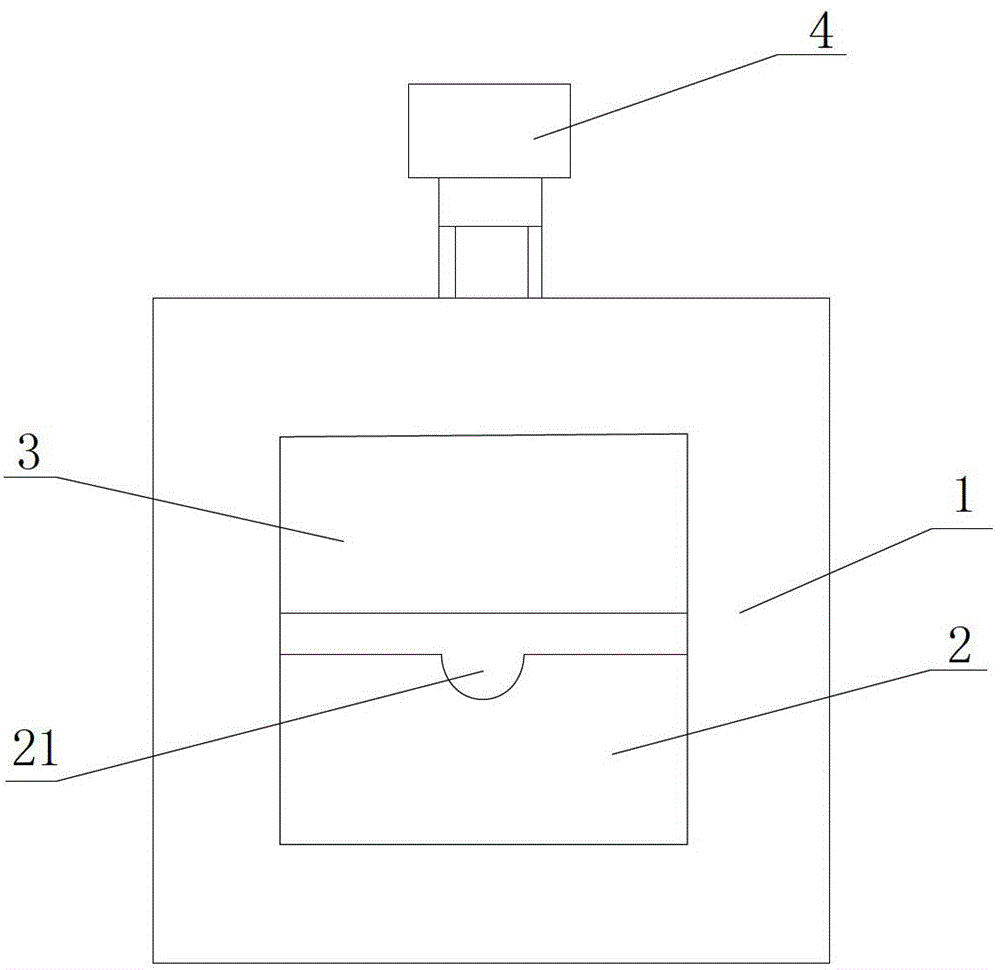
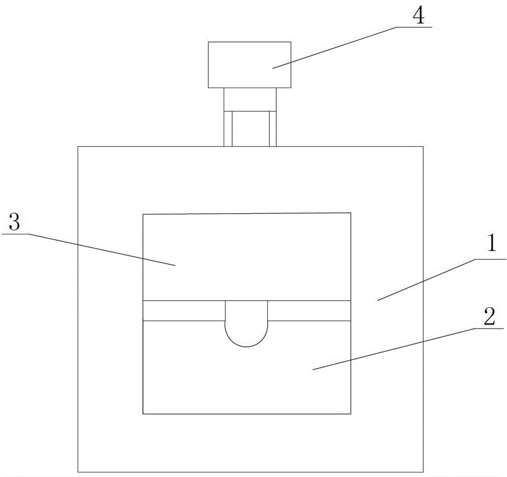
[0020] refer to Figure 1 to Figure 4 , a cemented carbide roller ring milling tool holder, including a base 1 with a rectangular hole 11, a lower clamping element 2 and an upper clamping element 3 for clamping a cemented carbide roller ring milling cutter, the The above-mentioned upper clamping element 3 and the lower clamping element 2 are installed in the rectangular hole 11, and a clamp for clamping the cemented carbide roller ring grooving cutter is provided between the lower clamping element 2 and the upper clamping element 3. device, a positioning device is provided between the lower clamping element 2 and the upper clamping element 3 to limit the relative movement of the lower clamping element 2 and the upper clamping element 3, and the base 1 is provided with a clamping device for clamping the upper clamping element 3 and the fastening device of the lower clamping element 2; the upper clamping element 3 and the lower clamping element 2 are cuboids with the same width ...


PUM


Abstract

The invention aims to disclose a fixture for a hard alloy roll collar slotting cutter. By the aid of the fixture, the problem of severe wastage of hard alloy roll collar slotting cutters in the prior art can be solved. The fixture comprises a base, a lower clamping element and an upper clamping element. The base is provided with a rectangular hole, the lower clamping element and the upper clamping element are used for clamping the hard alloy roll collar slotting cutter and are mounted in the rectangular hole, a clamping device used for clamping the hard alloy roll collar slotting cutter is arranged between the lower clamping element and the upper clamping element, a positioning device used for limiting relative movement of the lower clamping element and the upper clamping element is arranged between the lower clamping element and the upper clamping element, and a fastening device used for clamping the upper clamping element and the lower clamping element is arranged on the base. The fixture has the advantages that the problem that an existing hard alloy roll collar slotting cutter cannot be repaired after being damaged is solved, the fixture is simple in structure and low in manufacturing cost, and can be used conveniently and reliably, the cost can be saved, and the part machining precision can be improved.

Description

technical field [0001] The invention relates to a fixture, in particular to a cemented carbide roller ring groove milling cutter fixture. Background technique [0002] At present, although there are many types of fixtures, although a fixture described in Patent No. CN201120526660.5 has high processing efficiency, it cannot clamp the carbide roller ring groove cutter, and the carbide roller ring groove cutter is very difficult during use. It is easy to be damaged. The cemented carbide roller ring milling cutter is small in size and there is no special repair fixture. In order to avoid waste, the cemented carbide ring milling cutter will be utilized to the greatest extent until the carbide roller ring milling cutter cannot be used, which will make the processed parts less accurate. The price of the alloy roll ring groove cutter is relatively high, so this will increase the processing cost. Contents of the invention [0003] The invention provides a cemented carbide roller ...

Claims


Application Information

Patent Timeline
Patent Type & Authority Patents(China)
IPC IPC(8): B23Q3/00
CPCB23Q3/062
Inventor 黄椿郭伟波金益民吴晓娜
Owner ZHEJIANG HENGCHENG CEMENTED CARBIDE CO LTD
Features
  • R&D
  • Intellectual Property
  • Life Sciences
  • Materials
  • Tech Scout
  • Unparalleled Data Quality
  • Higher Quality Content
  • 60% Fewer Hallucinations
Learn More