Optical anti-vibration motor

An optical anti-shake, motor technology, applied in the direction of optics, optical components, installation, etc., can solve problems such as uneven thrust, affecting picture quality, jitter, etc., and achieve the effect of improving stability and good anti-shake performance

Inactive Publication Date: 2013-12-18
SHANGHAI BILLU ELECTRONICS CO LTD
View PDF12 Cites 21 Cited by
  • Summary
  • Abstract
  • Description
  • Claims
  • Application Information

AI Technical Summary

Problems solved by technology

[0006] Although the above-mentioned lens driving device can limit the movement of the lens support body through the reeds on both sides of the front and rear sides, so that it has the performance of resistance to bumps and impacts, but since the magnet and the coil are a whole, the difference between the magnet and the coil itself causes the conductive coil The thrust generated in the magnetic field is not uniform, so it will cause jitter and affect the picture quality

Method used


Image

  • Optical anti-vibration motor
  • Optical anti-vibration motor
  • Optical anti-vibration motor

Examples


Embodiment Construction

[0015] The present invention will be described in detail below in conjunction with the accompanying drawings and examples.

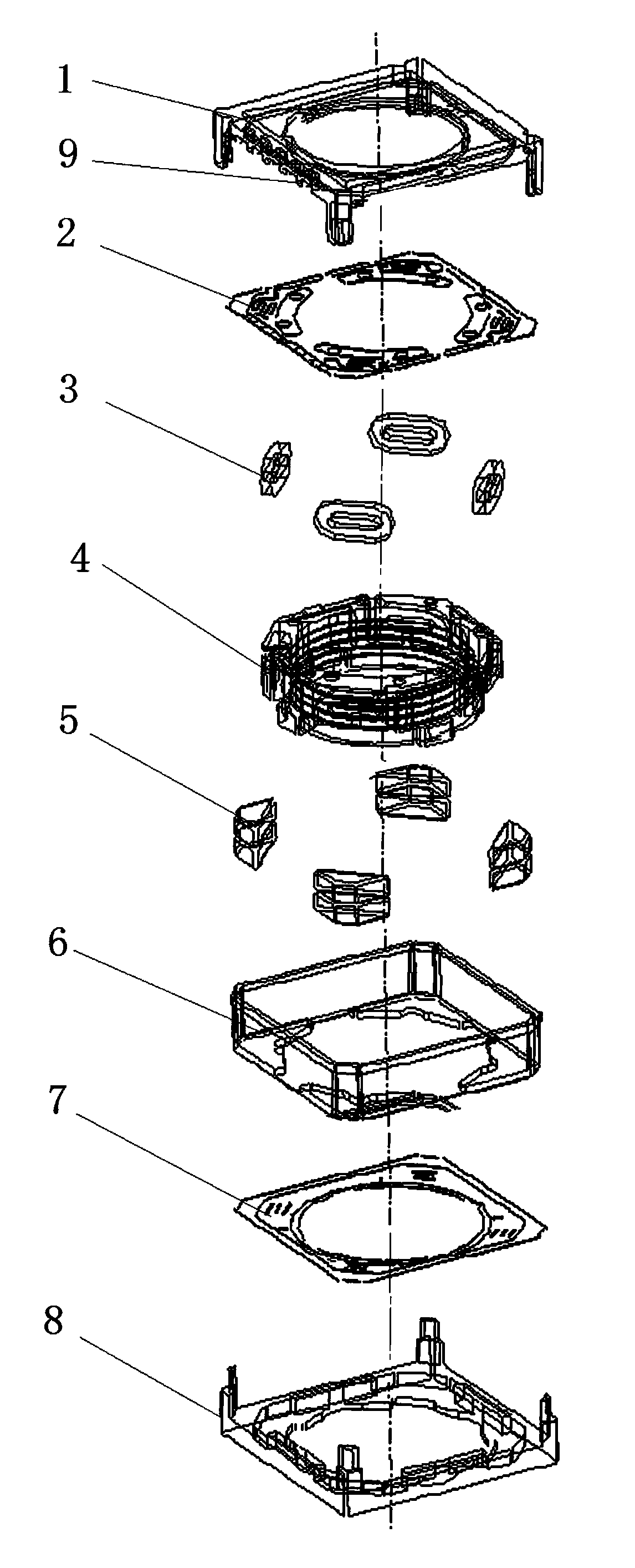
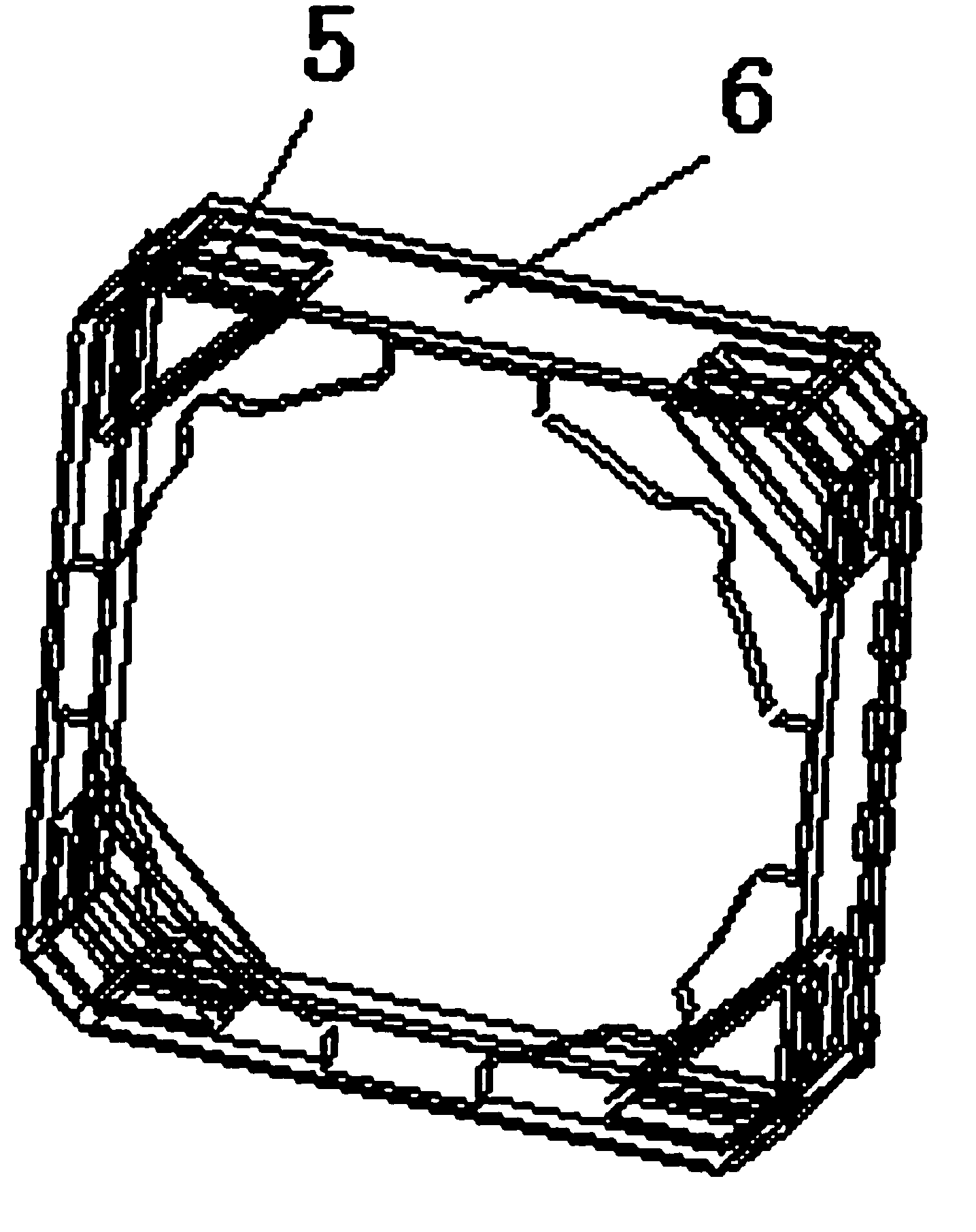
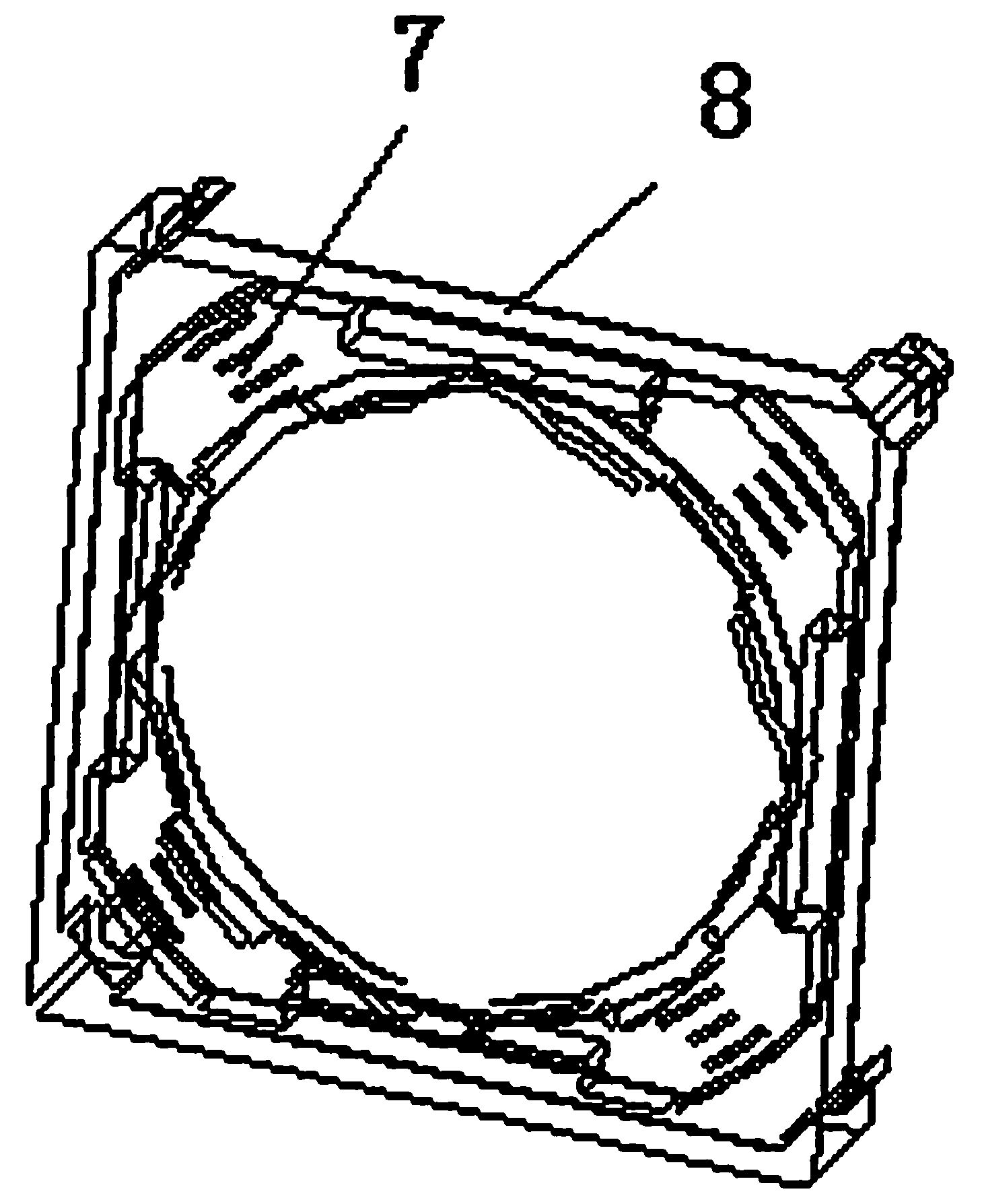
[0016] As shown in the figure, an optical anti-shake motor includes a base 1, a yoke iron shell 6 cooperating with the base 1, a magnet 5 and a lens carrier 4 wound with a coil 3 are arranged in the yoke iron shell 6, and the lens A rear reed 2 is provided between the carrier 4 and the base 1, and the yoke iron shell 6 is a square structure, which is characterized in that four groups of magnets 5 are arranged symmetrically on the yoke iron shell 6 of the square structure, and the outside of the lens carrier 4 Four coils 3 are arranged symmetrically, and each coil 3 corresponds to a group of magnets 5 . As shown in the figure, the coil is located between the magnet and the lens carrier 4, and the coil and the magnet are vertically arranged. There is also a PCB board 9 inside the base 1 , the PCB board 9 is provided with four control terminals, each contr...


PUM


Abstract

The invention discloses an optical anti-vibration motor. The optical anti-vibration motor comprises a base and a magnet yoke iron shell which is arranged with the base in a matching mode. Magnets and a lens carrier are arranged inside the magnet yoke iron shell, wherein coils are wound around the lens carrier. A rear spring piece is arranged between the lens carrier and the base and the magnet yoke iron shell is of a square structure. The optical anti-vibration motor is characterized in that four sets of magnets are symmetrically arranged on the magnet yoke iron shell of the square structure, the four coils are symmetrically arranged outside the lens carrier and each coil corresponds to one set of magnet. A PCB is further arranged inside the base, the PCB is provided with four control ends, each control end is electrically connected with one coil and the PCB is further provided with external pins. The optical anti-vibration motor has the advantages that the anti-vibration performance is good and the motion reliability of the lens carrier is improved.

Description

technical field [0001] The invention relates to a lens driving device, in particular to an optical anti-shake motor applied to a camera, a video camera or a mobile phone with a camera function to drive the lens to move and adjust the focal length. Background technique [0002] With the diversification of functions of digital products, digital devices equipped with video cameras or cameras, such as mobile phones, multimedia players, etc., have been developed rapidly and widely used. The above-mentioned video cameras or cameras usually adopt lenses with adjustable focal length or auto-focus, and the adjustment process is to change the position of the lens, and a drive motor is usually used to drive the lens to move. [0003] The driving device for adjusting the focal length of a traditional camera usually includes stepping motors, gears, cams, and connecting rods. A lens structure with a stable autofocus function disclosed in Chinese patent document CN2938165Y includes a housi...

Claims


Application Information

Patent Timeline
Patent Type & Authority Applications(China)
IPC IPC(8): G02B7/04G03B5/00H02K33/18G03B30/00
Inventor 王建华
Owner SHANGHAI BILLU ELECTRONICS CO LTD
Why Eureka
Try Eureka