
Bonded-magnet rotor, method of manufacturing thereof, and motor provided therewith

A technology of bonded magnets and manufacturing methods, which is applied in the manufacture of stator/rotor bodies, inductors/transformers/magnets, magnets, etc., which can solve the problem of unstable rotor shape accuracy, inability to form rotors with high precision, and changes in outer diameter dimensions, etc. question

Inactive Publication Date: 2013-12-18
PANASONIC CORP
View PDF10 Cites 6 Cited by
  • Summary
  • Abstract
  • Description
  • Claims
  • Application Information

AI Technical Summary

Problems solved by technology

Therefore, there is a problem that the shape accuracy of the rotor is not stable
[0013] In addition, when forming the rotor, there is also a problem that it is difficult to align the phase accuracy between the magnetization position (Japanese: magnetization position) of the main magnet piece fixed in the ring shape and the magnetization position of the magnet piece for positioning.
[0014] In addition, when the bonding method is used, for example, deviations in the accuracy of the bonding position of each magnet piece, eccentricity caused by bonding misalignment, fluctuations in the outer diameter of the bonding thickness, etc., will be caused by bonding. Problems unique to adhesives
As a result, there is a problem that the rotor cannot be formed with high precision

Method used


Image

  • Bonded-magnet rotor, method of manufacturing thereof, and motor provided therewith
  • Bonded-magnet rotor, method of manufacturing thereof, and motor provided therewith
  • Bonded-magnet rotor, method of manufacturing thereof, and motor provided therewith

Examples


Embodiment approach 1

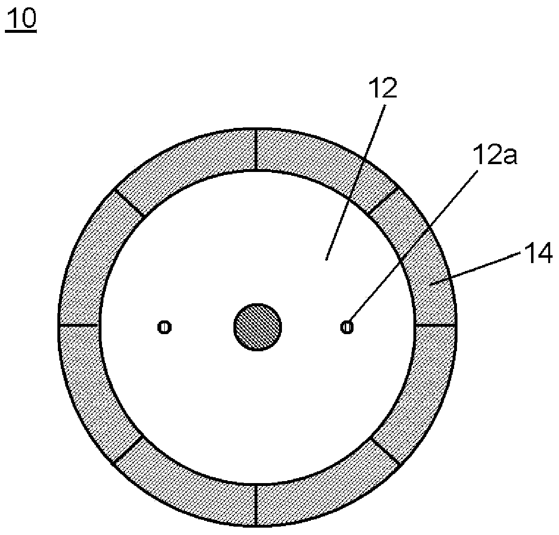
[0031] Below, use figure 1 A bonded magnet rotor manufactured by the method for manufacturing a bonded magnet rotor according to Embodiment 1 of the present invention will be described.

[0032] figure 1 It is a plan view showing an example of a bonded magnet rotor configured using a bonded magnet molded body according to Embodiment 1 of the present invention.

[0033] Such as figure 1 As shown, the bonded magnet rotor 10 according to Embodiment 1 is composed of a bonded magnet molded body 14, for example, 8 poles, and the bonded magnet molded body 14 is fixed to the outer periphery of a rotor core 12 made of, for example, laminated magnets. The structure is made of silicon steel plate. At this time, each bonded magnet molded body 14 is composed, for example, of NdFeB-based magnetic powder and SmFeN-based magnetic powder that have been anisotropically treated so as to have an easy axis of magnetization in the uniaxial direction. In the bonded magnet rotor constituted, o...


PUM

PropertyMeasurementUnit
softening pointaaaaaaaaaa
particle diameteraaaaaaaaaa
cure temperatureaaaaaaaaaa

Abstract

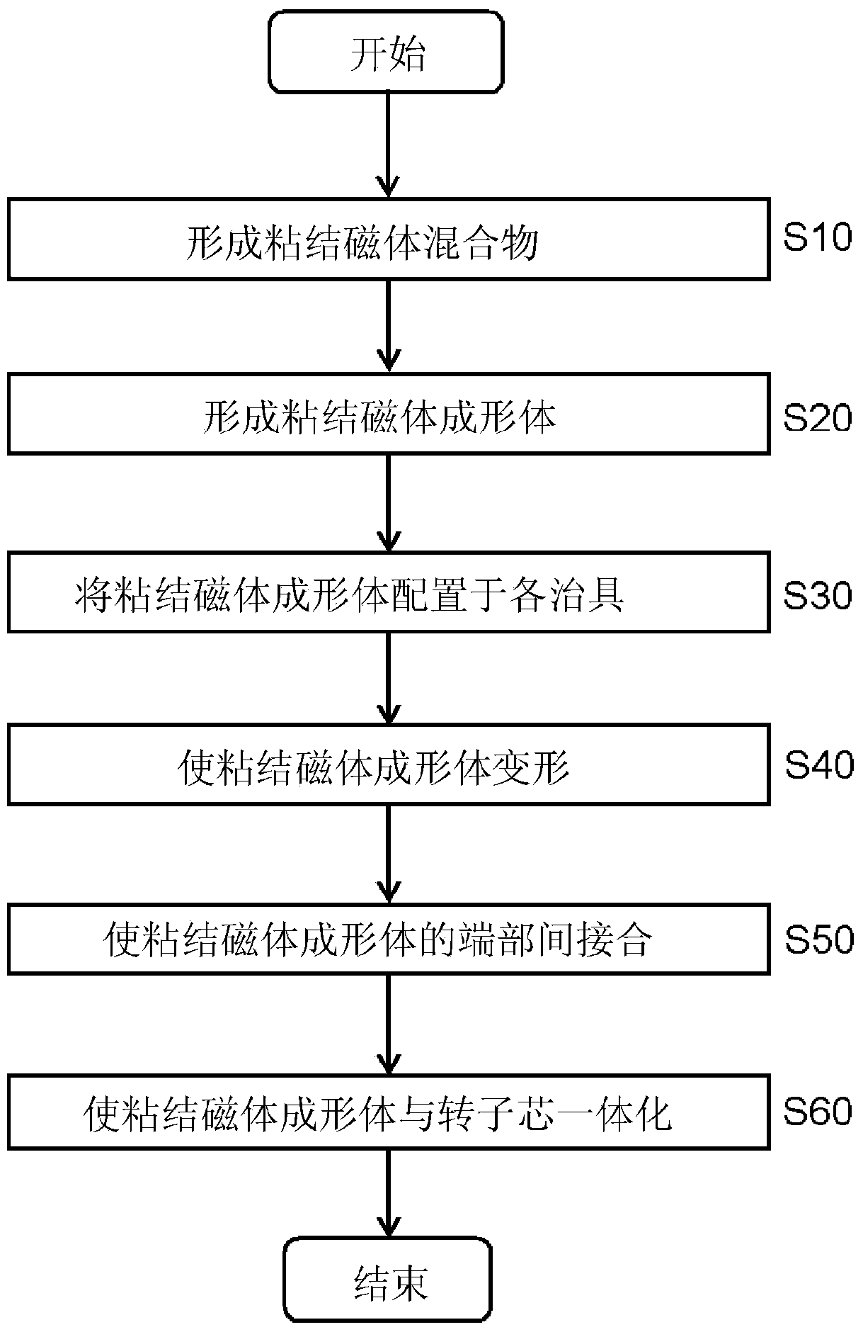
A method of manufacturing a bonded-magnet rotor of the present invention comprises: a step for forming bonded-magnet compacts; and an arranging step for integrating an inner-diameter supporting jig, a rotor core, and a rotor-core supporting jig, arranging the bonded-magnet compacts onto the outer circumference of the inner-diameter supporting jig, and arranging an outer-diameter supporting magnet-pressing jig for supporting the outer circumference face. The method of manufacturing a bonded-magnet rotor further comprises: a deformation step for pressing the bonded-magnet compacts with a molding jig to move the bonded-magnet compacts to the rotor core, and deforming the bonded-magnet compacts so as to match the outer circumference dimension of the rotor core; a joining step for joining end sections of adjacent bonded-magnet compacts with each other; and an integrating step for compressing the bonded-magnet compacts to integrate the bonded-magnet compacts with the rotor core. In such a way, bonded-magnet rotors with high precision in the shapes thereof can be attained.

Description

technical field [0001] The present invention relates to a bonded magnet rotor, a manufacturing method thereof, and a motor having the bonded magnet rotor. Background technique [0002] The permanent magnet, which is one of the components of the motor, is used in various forms as shown below depending on the application and specifications. For example, there are rotors in which permanent magnets are fixed to the surface of the rotor core, and rotors in which permanent magnets of a predetermined shape are arranged and fixed inside the rotor core. At this time, the fixed permanent magnet can be selected from various materials such as sintered magnets and bonded magnets having different magnetic properties according to the required motor performance. In addition, as for the shape of the permanent magnet, various shapes such as a plate-shaped magnet, an arc-shaped tile-shaped magnet, or a ring-shaped magnet can be employed. [0003] In addition, permanent magnets are effectivel...

Claims


Application Information

Patent Timeline
Patent Type & Authority Applications(China)
IPC IPC(8): H02K15/03H01F7/02H01F41/02
CPCH02K15/03H01F7/021H01F41/0266Y10T29/49012H02K1/28H02K15/0012
Inventor 浅井弘纪
Owner PANASONIC CORP
Learn More