Three-section variable magnetic circuit series-parallel connection adjustable magnetic flux motor

A magnetic flux motor, three-stage technology, applied in the field of wide speed regulation

Active Publication Date: 2022-05-13
HARBIN INST OF TECH
View PDF5 Cites 0 Cited by
  • Summary
  • Abstract
  • Description
  • Claims
  • Application Information

AI Technical Summary

Problems solved by technology

[0004] Aiming at the problems existing in the existing adjustable flux motor, the present invention provides a three-stage variable magnetic circuit series-parallel adjustable flux motor

Method used


Image

  • Three-section variable magnetic circuit series-parallel connection adjustable magnetic flux motor
  • Three-section variable magnetic circuit series-parallel connection adjustable magnetic flux motor
  • Three-section variable magnetic circuit series-parallel connection adjustable magnetic flux motor

Examples


specific Embodiment approach 1

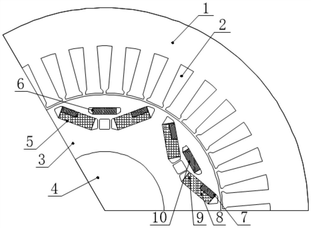
[0031] Specific implementation mode one: the following combination Figure 1 to Figure 4 This embodiment is described. The three-stage variable magnetic circuit series-parallel adjustable flux motor described in this embodiment includes a stator core 1, a stator winding 2, a rotor core 3 and a rotating shaft 4; the rotor core 3 is fixed on the rotating shaft 4, and Located inside the stator core 1, the armature winding 2 is arranged on the stator core 1;

[0032] Also includes series-parallel adjustable magnetic poles, the series-parallel adjustable magnetic poles include No. 1 high-coercivity permanent magnet 7, No. 1 low-coercivity permanent magnet 8, No. 2 low-coercivity permanent magnet 9 and No. 2 high-coercivity permanent magnet Coercive permanent magnet 10;

[0033]A V-shaped permanent magnet slot 5 and a flat-shaped permanent magnet slot 6 are arranged under each pole of the rotor core 3, and a flat-shaped permanent magnet slot 6 is arranged in the opening of the V-sh...

specific Embodiment approach 2

[0048] Specific embodiment two: This embodiment will further explain embodiment one, No. 1 high-coercivity permanent magnet 7, No. 1 low-coercivity permanent magnet 8, No. 2 low-coercivity permanent magnet 9 and No. 2 high-coercivity permanent magnet The setting mode of force permanent magnet 10:

[0049] The No. 1 high-coercive force permanent magnet 7 and the No. 2 high-coercive force permanent magnet 10 are both integral permanent magnets, or consist of multiple permanent magnets along the axial direction.

[0050] The No. 1 low-coercive force permanent magnet 8 and the No. 2 low-coercive force permanent magnet 9 are of two-stage split structure or integral structure, and adopt a single permanent magnet or consist of multiple permanent magnets along the axial direction. The No. 1 low-coercivity permanent magnet 8 and the No. 2 low-coercivity permanent magnet 9 can be two independent permanent magnets, or two parts of a whole permanent magnet.

specific Embodiment approach 3

[0051] Embodiment 3: In this embodiment, Embodiment 1 is further explained. A magnetic bridge is set at the symmetry axis of the V-shaped permanent magnet slot 5 under each pole, and between the outer magnetic pole and the circumference of the rotor.


PUM


Abstract

The invention discloses a three-section type variable magnetic circuit series-parallel connection adjustable magnetic flux motor, belongs to the field of permanent magnet motors, and aims at solving the problems of an existing adjustable magnetic flux motor. The motor comprises a stator core, a stator winding, a rotor core and a rotating shaft. The rotor iron core is fixed on the rotating shaft and located in the stator iron core, and the armature winding is arranged on the stator iron core; the series-parallel connection adjustable magnetic pole comprises a first high-coercive-force permanent magnet, a first low-coercive-force permanent magnet, a second low-coercive-force permanent magnet and a second high-coercive-force permanent magnet; a V-shaped permanent magnet groove and a linear permanent magnet groove are arranged below each pole of a rotor iron core, symmetry axes of the two permanent magnet grooves coincide, a pair of first high-coercive-force permanent magnets and a pair of first low-coercive-force permanent magnets which are connected in series are symmetrically installed in the V-shaped permanent magnet grooves close to the air gap side, and a pair of second low-coercive-force permanent magnets are symmetrically installed in the V-shaped permanent magnet grooves away from the air gap side. Second high-coercivity permanent magnets are installed in the linear permanent magnet grooves.

Description

technical field [0001] The invention relates to wide speed regulation technology of variable magnetic circuit series-parallel adjustable magnetic flux motors, and belongs to the field of permanent magnet motors. Background technique [0002] Due to the advantages of high power density and high efficiency, traditional permanent magnet synchronous motors are often used in the drive system of new energy vehicles. However, this type of motor has disadvantages such as difficult adjustment of the permanent magnet magnetic field, limited speed expansion range, and low efficiency when the field is weakened. . In response to the above problems, scholars have proposed an adjustable flux motor with an adjustable permanent magnet magnetic field. This motor can change the magnetization state of the permanent magnet by applying d-axis charging and demagnetizing pulse currents, thereby expanding the speed range of the motor. the goal of. Unlike adjustable flux motors that only use one lo...

Claims


Application Information

Patent Timeline
Patent Type & Authority Applications(China)
IPC IPC(8): H02K1/276H02K21/14H02K21/02
CPCH02K1/276H02K1/2766H02K21/14H02K21/021H02K2213/03H02K2201/03Y02T10/64
Inventor 王明峤郑萍佟诚德乔光远梁晓宇刘法亮
Owner HARBIN INST OF TECH
Why Eureka
Try Eureka