
Eureka
For R&D, Eureka makes reading and utilizing patents & technical documents easy.
Eureka AIR
Designed for self-driven R&D workflows. Generate viable solutions, solve complex R&D challenges, empower your innovation with AI.

Eureka Materials
Designed for material experts only. Revolutionize your material R&D, from search, analyze, to developing new materials.

TechResearch
Generate reliable direction feasibility study reports for your R&D in just a few steps.

TechSeek
Discover and master advanced knowledge NOW. Basics, ideas, possibilities, all at once.

TechMind
As an expert in R&D Theories, TechMind can generates customized viable solutions instantly.

TechRisk
Analyze your overall solution with one click, know your potential R&D risks in advance.

TechMonitor
Get weekly tech updates, stay abreast of the latest tech innovations and key insights.
Electromechanical actuator lubrication system for ram air turbine
A technology of actuators and gas turbines, which is used in auxiliary power equipment, aircraft transmissions, aircraft power transmission, etc., and can solve problems such as leakage, pressure increase, and fluid leakage
- Summary
- Abstract
- Description
- Claims
- Application Information
AI Technical Summary
Problems solved by technology
Method used
Image

Examples
Embodiment Construction
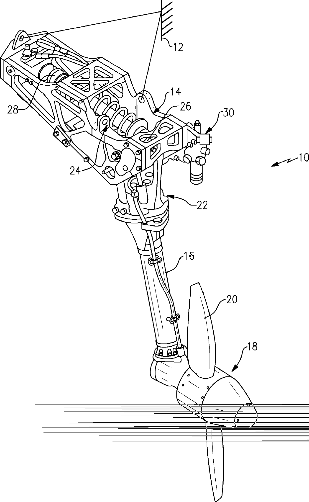
[0012] figure 1 RAT system 10 is shown secured to aircraft structure 12 by housing 14 . The housing 14 pivotably supports a strut 16 having a turbine 18 at one end. The turbine 18 includes blades 20 that impart rotational drive to, for example, a generator 22 and a hydraulic pump 30 . The actuator 24 is secured to the strut 16 at a first end 26 and to the housing at a second end 28 . Actuator 24 is shown in its deployed position.
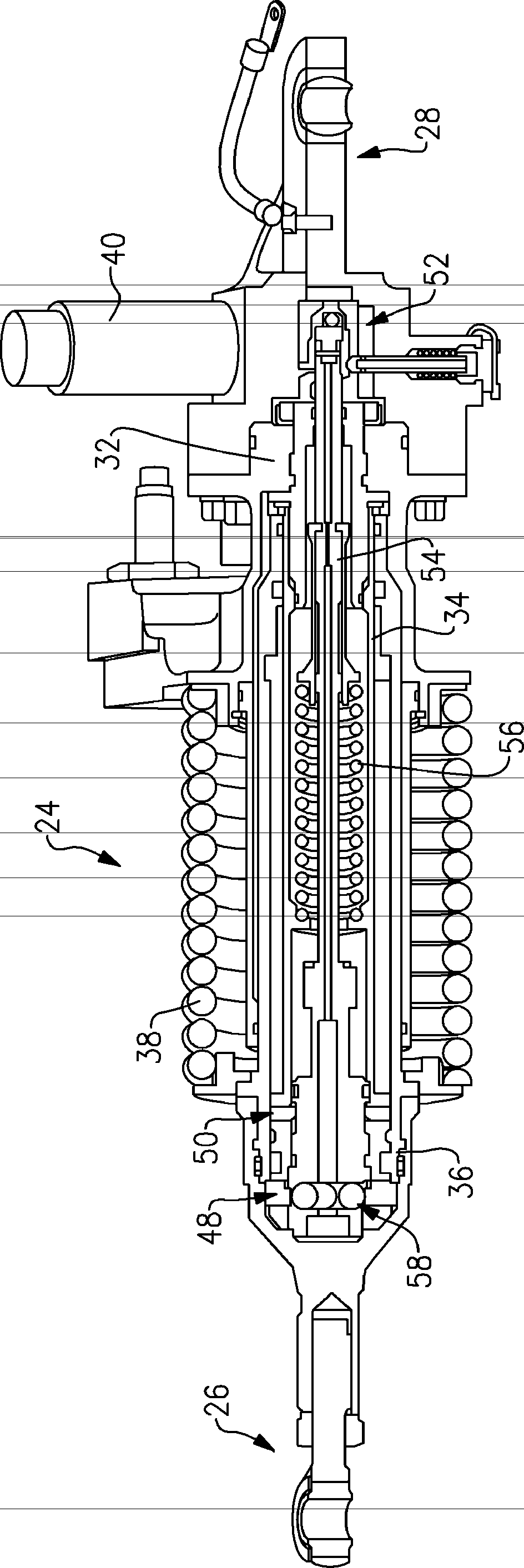
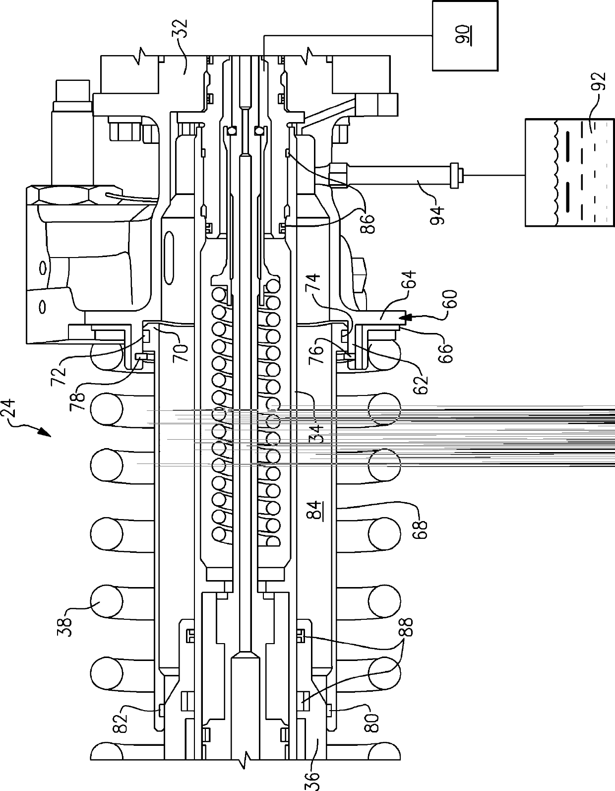
[0013] refer to figure 2 and image 3 , the actuator 24 comprises a housing 32 having a piston rod 34 and a cylinder 36 not attached to the housing 32, the piston rod 34 and the cylinder 36 being telescopically arranged relative to each other. Deployment spring 38 is arranged between housing 32 and cylinder 36, under compression, actuator 24 is in its retracted position, as figure 2 shown. A piston rod 34 is fixed to the housing 32 and a cylinder 36 is arranged to slide on the piston rod 34 .
[0014] The piston rod 34 supports an upper lo...
PUM
 Abstract
Description
Claims
Application Information
 - R&D Engineer
- R&D Manager
- IP Professional
- Industry Leading Data Capabilities
- Powerful AI technology
- Patent DNA Extraction
Browse by: Latest US Patents, China's latest patents, Technical Efficacy Thesaurus, Application Domain, Technology Topic, Popular Technical Reports.
© 2024 PatSnap. All rights reserved.Legal|Privacy policy|Modern Slavery Act Transparency Statement|Sitemap|About US| Contact US: help@patsnap.com