Externally adjustable internal bypass shock absorber

a shock absorber and external adjustment technology, applied in the direction of shock absorbers, vibration dampers, springs/dampers, etc., can solve the problems of major drawbacks of shock absorbers, inability to use one, and the shock has to be removed from the vehicle and disassembled

Active Publication Date: 2007-09-18
AYMAR BRANDON
View PDF11 Cites 52 Cited by
  • Summary
  • Abstract
  • Description
  • Claims
  • Application Information

AI Technical Summary

Benefits of technology

[0009]It is also an object of the invention to provide a novel shock absorber that has bypass passageways whose hydraulic fluid flow can be increased or decreased by external mechanical structure to vary the damping characteristics.

Problems solved by technology

The problem with current products on the market is:
However, the shock has to be removed from the vehicle and disassembled to adjust the damping within the shock.
This is the major drawback to this shock.
It isn't practical when one wants to adjust the shocks on demand and out in the field.

Method used


Image

  • Externally adjustable internal bypass shock absorber
  • Externally adjustable internal bypass shock absorber
  • Externally adjustable internal bypass shock absorber

Examples


Embodiment Construction

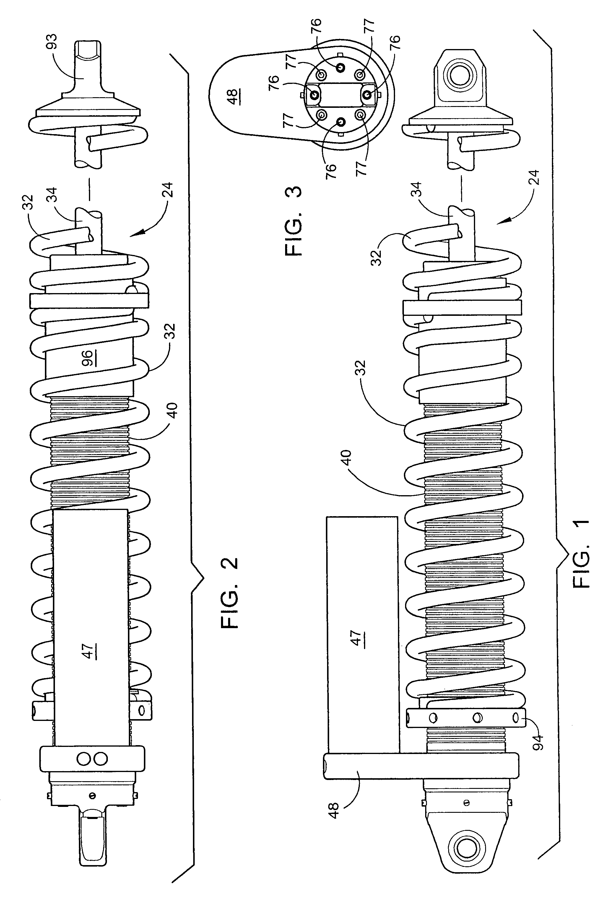
[0047]The externally adjustable internal bypass shock absorber will now be described by referring to FIGS. 1-19 of the drawings. The shock absorber is generally designated numeral 24. FIGS. 1-3 show the shock absorber 24 completely assembled. The invention will be more easily understood by specifically describing the individual components and assemblies. This will be done by referring to the other drawings.

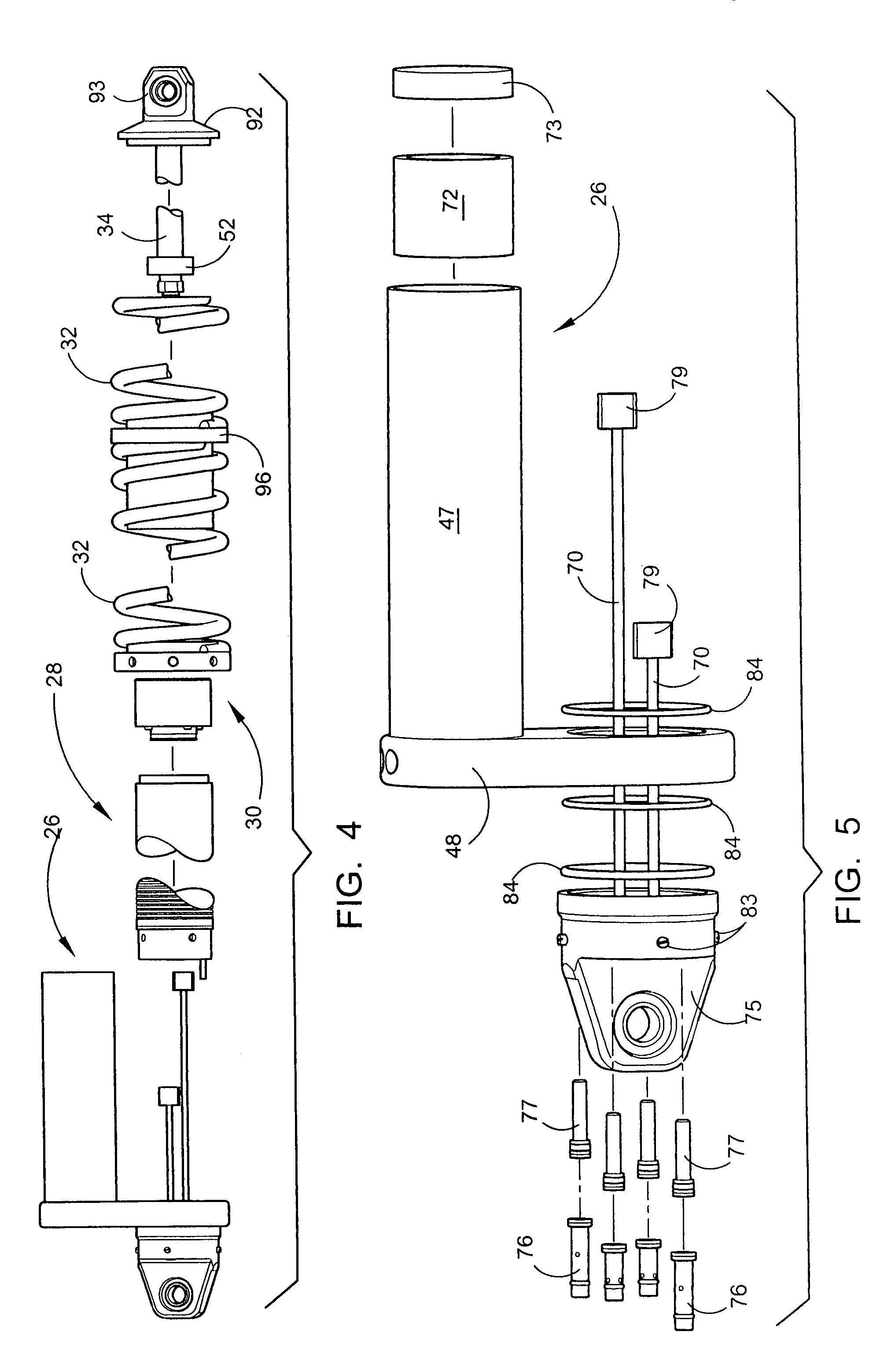
[0048]FIG. 4 is an exploded front perspective view of shock absorber 24. Numeral 26 identifies the top assembly (see FIG. 5). Numeral 28 identifies the main body assembly (see FIG. 6). The main seal body and assembly 30 is illustrated in FIG. 11. The coil spring 32 and its associated structure are illustrated in FIG. 12. The piston rod 34 and its associated structure are illustrated in FIG. 13.

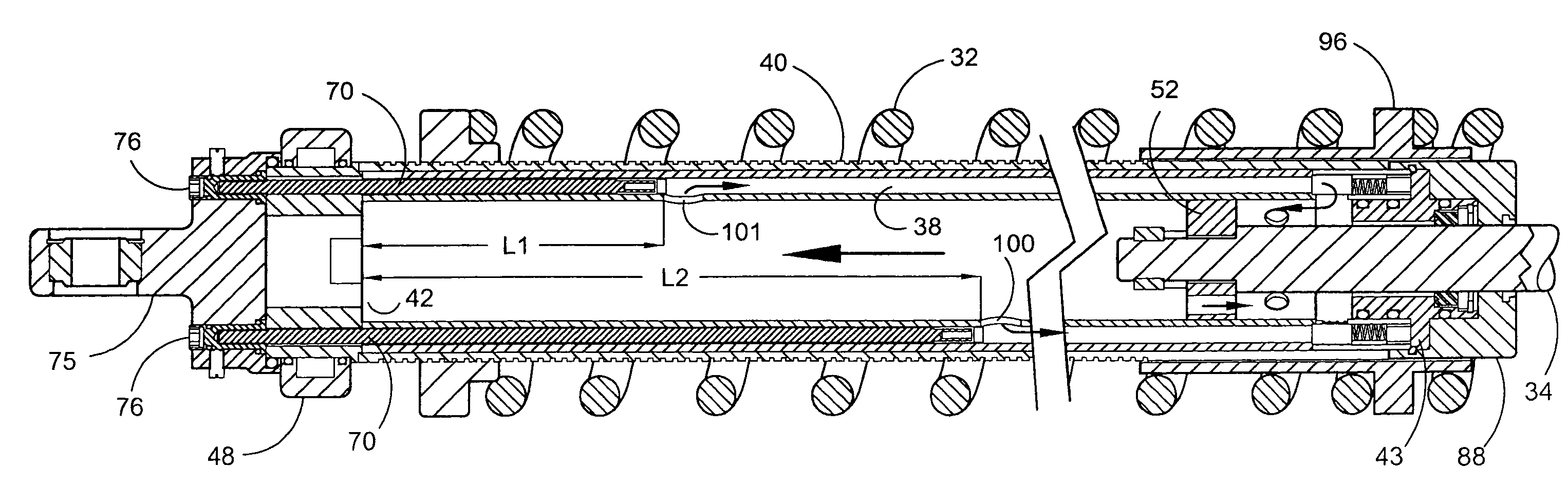
[0049]The basic components of the shock absorber are clearly illustrated in FIG. 6. The shock body 36 is a hollow cylinder having an outer diameter D1. A plurality of bypass tubes or channel...


PUM


Abstract

A shock absorber that combines both the suspension function and the shock absorbing function in one unit. It has an elongated shock body filled with hydraulic fluid and a piston mounted on a piston rod that reciprocally travels within the shock body. The shock body is telescopically received in a bypass cylinder body having a greater diameter that produces an annular chamber between the outer surface of the shock body and the inner surface of the bypass cylinder body. A coil spring is mounted on the outside surface of the bypass cylinder body to provide a suspension function by the shock absorber. A plurality of bypass tubes are associated with longitudinally spaced ports in the shock body. Adjuster rods are telescopically received inside the respective bypass tubes for controlling whether the individual ports are closed, partially open, or fully open. These adjuster rods would be manipulated externally of the shock absorber assembly.

Description

[0001]This application claims the priority of U.S. Provisional Patent Application Ser. No. 60 / 555,837 filed Mar. 23, 2004.BACKGROUND OF THE INVENTION[0002]Many types of suspensions and supports include a spring and a damping device to help isolate that supported from the support structure or surface. For example, automotive vehicles commonly use separate springs and simple shock absorbers to support the vehicle frame on the axle assemblies. Simple shock absorbers are typically oil-filled cylinders within which a vented piston is mounted. The piston is connected to a shaft which extends out of one end of the cylinder. The outer end of the shaft is mounted to one point on the vehicle and the other end of the cylinder is mounted to another point on the vehicle in parallel with the suspension spring. Thus, simple shock absorbers only provide damping and not support.[0003]Another type of shock absorber, which is the type commonly used with motorcycles, off-road vehicles, competition auto...

Claims


Application Information

Patent Timeline
Patent Type & Authority Patents(United States)
IPC IPC(8): F16F9/48
CPCF16F9/461
Inventor AYMAR, BRANDON
Owner AYMAR BRANDON
Why Eureka
Try Eureka