Trigger mechanism of a repeating rifle

a repeating rifle and trigger mechanism technology, applied in the direction of firing/trigger mechanism, breech mechanism, weapon components, etc., can solve the problems of inability to change the trigger characteristics, risk of conventional trigger and sear system, etc., to achieve easy modification, increase tolerance, and facilitate production

Active Publication Date: 2012-05-17
BLASER FINANZHLDG
View PDF7 Cites 5 Cited by
  • Summary
  • Abstract
  • Description
  • Claims
  • Application Information

AI Technical Summary

Benefits of technology

[0004]In one embodiment, a problem to be solved by the present invention is to make available a trigger mechanism of the aforementioned type, which can be produced inexpensively, which allows the trigger characteristics to be changed simply and easily, and which ensures excellent functionality and high safety even under extreme conditions.
[0006]In the trigger mechanism according to the present invention, the bolt lock which is dedicated to a sear nose for holding or releasing a firing pin assembly is pivoted about an axis of rotation on the sear nose. The counter sear which interacts with the sear on the bolt lock, on the other hand, is disposed on a stationary sear element. Using this type of assembly, it is possible to ensure the functionality of the trigger mechanisms with components that can be readily produced and that have larger tolerances. The components responsible for locking the sears can be easily modified, thereby making it possible to vary the trigger characteristics. In addition, the sear depth is ensured even if the range of tolerance is wide. The trigger mechanism makes it possible to securely lock the sears and provides especially secure protection against a release of the trigger in the drop test.
[0007]In an especially useful embodiment, the bolt lock is actuated by a compression spring that is disposed in the sear nose in such a manner that the sear on the bolt lock is pushed in the direction of the counter-sear. Because of the elastic pre-tension of the bolt lock, friction-mediated automatic locking takes place, which ensures excellent drop security and high protection against undesirable firing of a shot. The compression spring is integrated into the sear nose, which makes for compact construction.
[0008]The pre-tension of the compression spring can preferably be changed by means of an adjusting screw or another type of adjusting element. This makes it possible to adjust the trigger pull without having to dismount the compression spring in the sear nose.
[0009]In another useful embodiment of the invention, a control surface that meshes with a return cam on the stationary sear element is disposed on the bolt lock so as to be able to forcibly reset the bolt lock into the sear position. By means of the return cam and the control surface formed on the bolt lock to mesh with this return cam, it is also possible to forcibly reset the trigger mechanism if automatic resetting of the trigger element, which is normally effected by return springs, does not properly function, e.g., due to freezing, breakage of the spring, contamination or the like. Forcibly resetting the trigger element can be initiated, e.g., by moving the firing pin assembly, which normally occurs when the locking bolt mechanism is opened, which leads to additional safety.
[0010]The stationary sear element and the sear nose with the bolt lock which is pivotably disposed on the sear nose are preferably disposed in an insert. This makes it possible to simply incorporate the entire trigger unit in a receiver and, if required, also to quickly dismount and / or replace it.

Problems solved by technology

Because of the narrow tolerances and the necessary accurate interaction, changes to the trigger characteristics cannot be made without entailing certain problems.
In addition, in particular, extreme conditions, such as high contamination, resinification or freezing, may lead to malfunctions.
Under the aforementioned extreme conditions, the residual risk of the conventional trigger and sear systems is that after the trigger is pulled, the sear nose remains in its position and does not release the firing pin.

Method used


Image

  • Trigger mechanism of a repeating rifle
  • Trigger mechanism of a repeating rifle
  • Trigger mechanism of a repeating rifle

Examples


Embodiment Construction

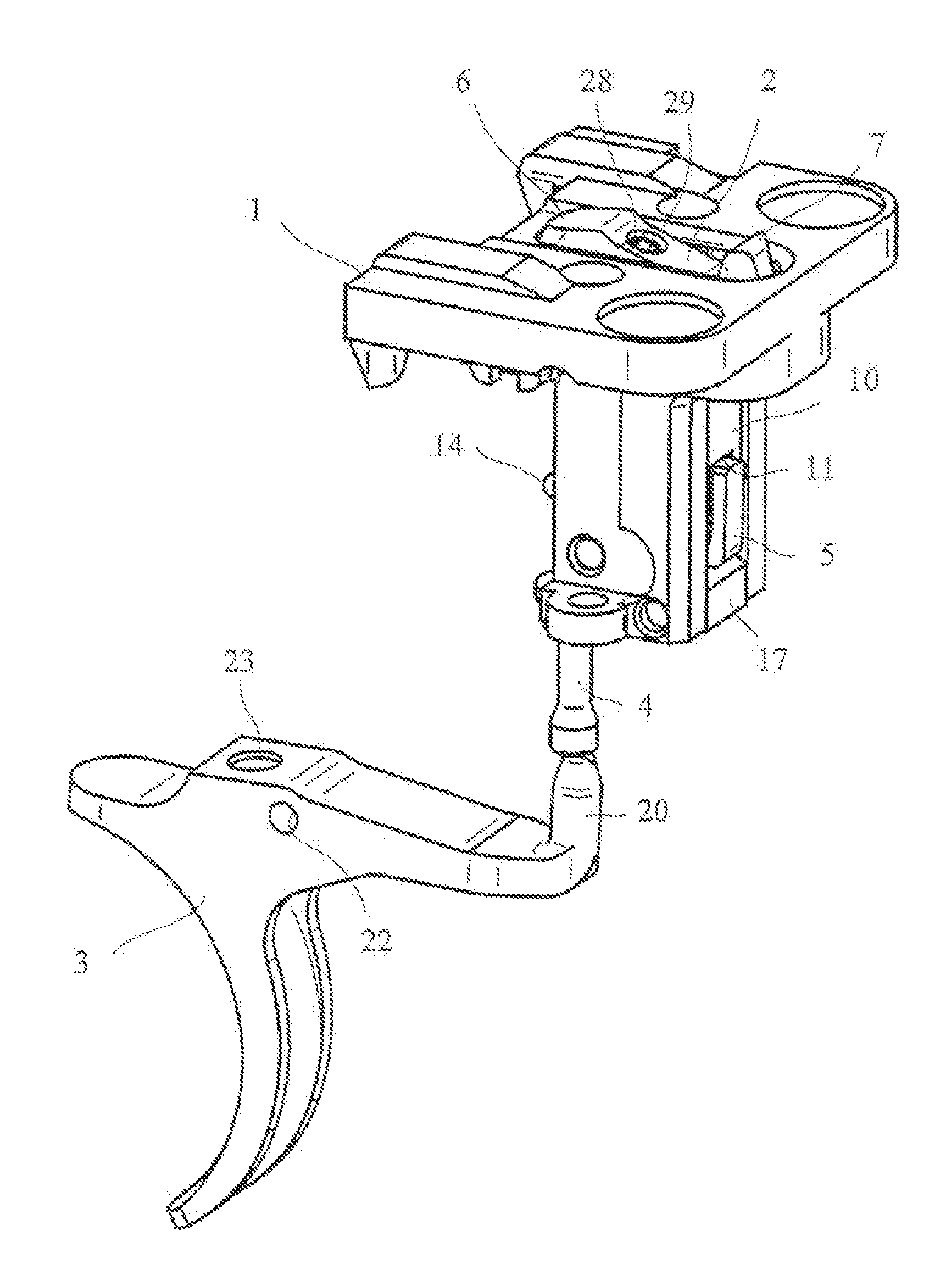
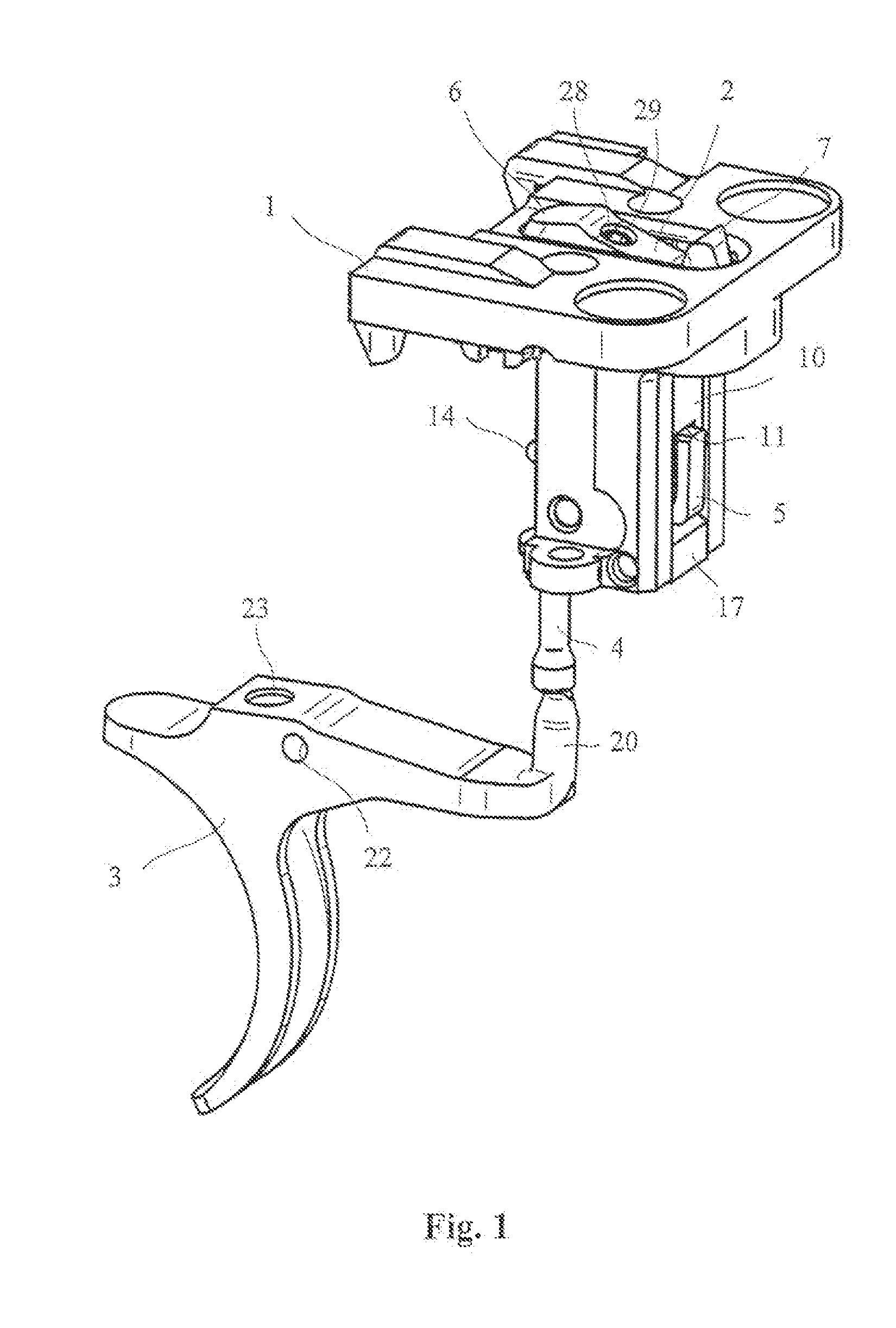
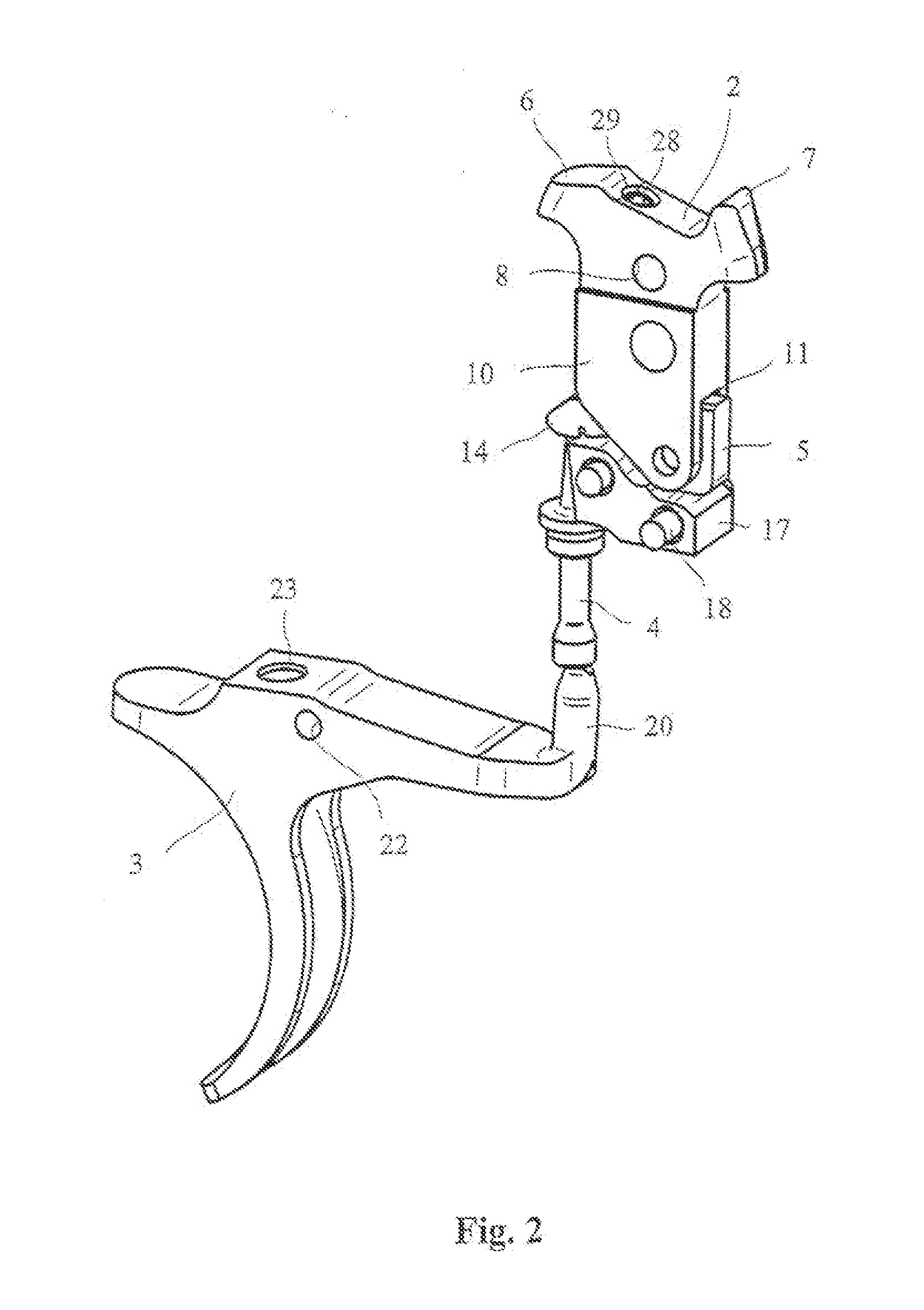
[0017]The trigger mechanism shown in a perspective view in FIG. 1 comprises a sear nose 2 which is pivotably disposed within an insert 1 and which, via a pin-shaped connecting element 4 and a bolt lock 5, can be actuated by means of a trigger 3 which is pivotably disposed within a receiver of a repeating rifle.

[0018]The sear nose 2 makes it possible for a firing pin assembly (not shown) of the repeating rifle to be held in a cocked position and / or to be released for firing a shot. To this end, the sear nose 2 comprises a front nose 6 by means of which, e.g., a firing pin nut that is disposed on the end of a firing pin can be pushed upward against a stationary central axis, and thus the firing pin biased by a spring can be held in a cocked position in a manner known in the art. In addition, a rear return nose 7 which will be explained in greater detail below is disposed on the upper surface of the sear nose 2. By means of a return spring (not shown), the sear nose 2 is pre-tensioned ...


PUM


Abstract

The present invention relates to a trigger mechanism of a repeating rifle, comprising a sear nose (2) that pivots about an axis (9) and a bolt lock (5) which is dedicated to the sear nose (2) and which is connected to a trigger (3) that pivots about a trigger axis (21) and comprises a sear (15) that meshes with a counter-sear (16). To make it possible to change the trigger characteristics simply and easily, the counter-sear (16) is disposed on a stationary sear element (17) and the bolt lock (5) is disposed on the sear nose (2) so as to be pivotable about an axis of rotation (13).

Description

CROSS REFERENCE TO RELATED APPLICATION[0001]This application claims priority under 35 U.S.C. §119 to German Patent Application No. 10 2010 051 641.4 filed Nov. 17, 2010, the entire contents of which are incorporated herein by reference.FIELD OF THE INVENTION[0002]The present invention relates to a trigger mechanism of a repeating rifle.BACKGROUND OF THE INVENTION[0003]In conventional trigger and sear mechanisms, the trigger lever has a sear which, in the cocked position, is supported by a counter-sear of a trigger leaf. When a shot is triggered in this type of trigger and sear system, the sears disengage and the trigger elements are separated from one another. In the prior-art trigger systems, the sear and the counter-sear must be manufactured with utmost precision and must be accurately matched to each other in order to obtain the trigger characteristics required. Because of the narrow tolerances and the necessary accurate interaction, changes to the trigger characteristics cannot ...

Claims


Application Information

Patent Timeline
Patent Type & Authority Applications(United States)
IPC IPC(8): F41A19/10F41A3/38F41A19/12
CPCF41A19/16F41A19/12
Inventor POPIKOV, SERGIEJ
Owner BLASER FINANZHLDG
Why Eureka
Try Eureka