
Liquid crystal display apparatus and method of driving the same

Inactive Publication Date: 2006-11-23
NEC CORP
View PDF6 Cites 7 Cited by
  • Summary
  • Abstract
  • Description
  • Claims
  • Application Information

AI Technical Summary

Benefits of technology

[0018] It is, therefore, an object of the present invention to provide a data line drive circuit which can vary input-output characteristics without increasing an accuracy of a DAC circuit and eliminate production of luminance irregularities in a screen of a liquid crystal display apparatus. It is another object of the present invention to provide a liquid crystal display apparatus which can display an image having no luminance irregularities in a screen.
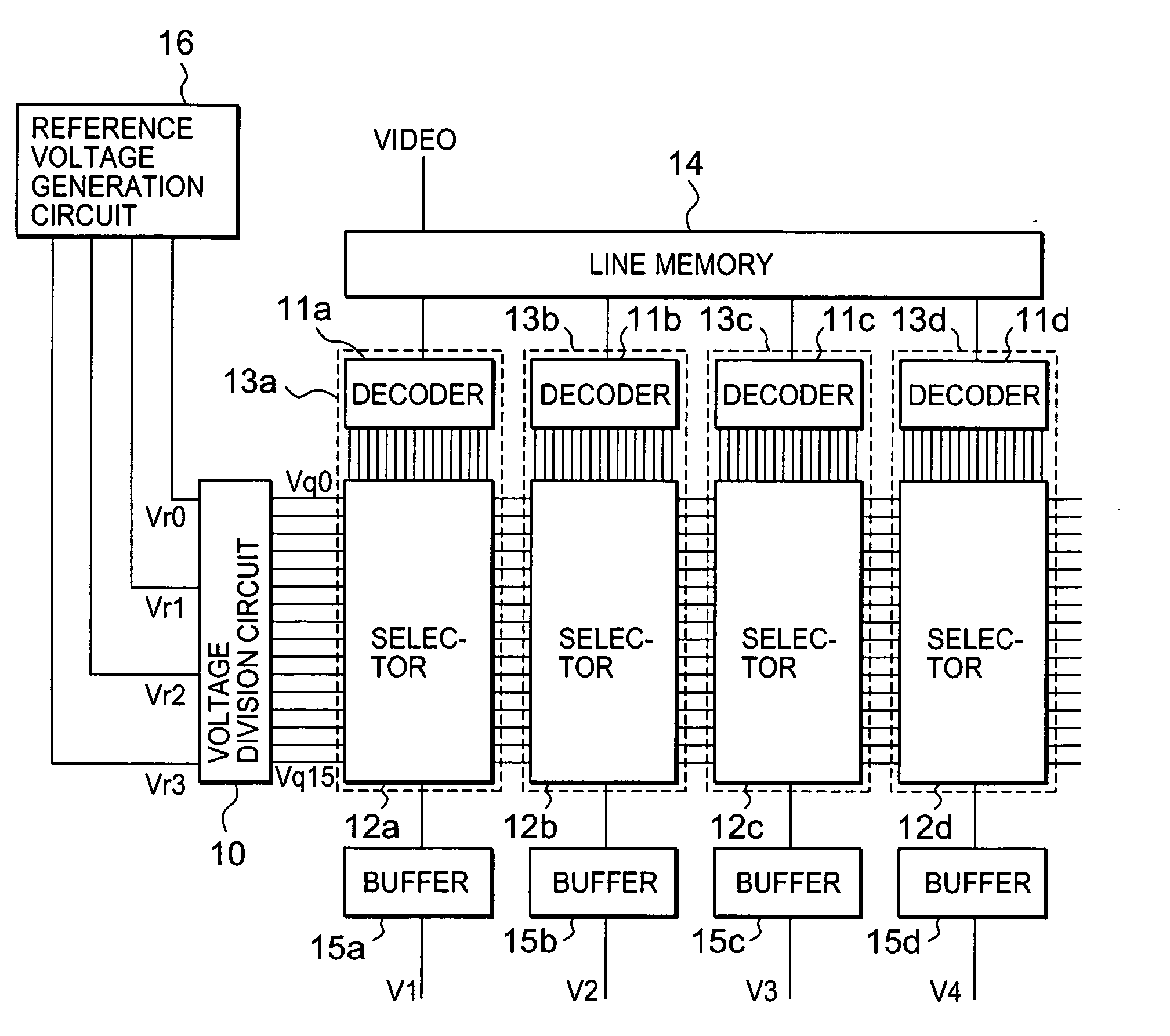
[0021] Reference voltages generated by the reference voltage generation circuit can be adjusted to set potentials of the nodes of the resistances at desired values. Consequently it is possible to obtain the nonlinear DAC circuit which can change input-output characteristics of the DAC circuit into desired characteristics.
[0022] Even if a display device has different gammas from position to position, it is possible to reduce positional luminance irregularities by using a plurality of such nonlinear DAC circuits in a data line drive circuit.
[0037] According to the present invention, reference voltages to determine the V-T characteristics are dynamically varied so as to vary the V-T characteristics depending upon positions of the pixels into which video signals are to be written in the liquid crystal display apparatus. Therefore, it is possible to reduce the luminance irregularities in the screen of the liquid crystal display apparatus. The luminance irregularities in the screen of the liquid crystal display apparatus are caused because the same V-T conversion is performed on all video signals to be written into pixels in the liquid crystal display apparatus although the V-T characteristics of the liquid crystal display apparatus have positional dependency. Accordingly, by varying V-T characteristics for video signals depending upon pixels into which the video signals are to be written, it becomes possible to reduce luminance irregularities.
[0038] Further, according to the present invention, it is possible to reduce the size of circuits. A conventional data line drive circuit capable of varying V-T characteristics employs DACs having linear input-output characteristics and performs arithmetic V-T conversion on digital signals. In this case, the conventional data line drive circuit should use DAC circuits having an accuracy of at least 10 bits in order to obtain outputs having a high accuracy corresponding to nonlinear V-T characteristics of a liquid crystal display apparatus. In contrast thereto, the data line drive circuit according to the present invention employs DAC circuits having nonlinear input-output characteristics and dynamically varies reference voltages of the voltage division circuit so as to vary input-output characteristics of the DAC circuits. Thus, the data line drive circuit according to the present invention can cope with variations of the V-T characteristics in the liquid crystal display apparatus. With this arrangement, an accuracy of about 8 bits is sufficient for the DAC circuits, and thus it is possible to reduce the size of circuits as compared to the conventional data line drive circuit.

Problems solved by technology

However, the gamma correction circuit of Patent Document 1 cannot change gamma correction characteristics according to positions in the panel.
However, because the DAC circuit of Patent Document 1 has nonlinear outputs, color irregularities cannot be eliminated only by varying input signals.
Thus, cost for IC is increased.
Thus, cost for IC is inevitably increased.

Method used


Image

  • Liquid crystal display apparatus and method of driving the same
  • Liquid crystal display apparatus and method of driving the same
  • Liquid crystal display apparatus and method of driving the same

Examples


example 1

[0080]FIG. 15 shows a first example of the data line drive circuit according to the present invention. FIG. 16 shows a liquid crystal display apparatus to be driven by the data line drive circuit shown in FIG. 15. The liquid crystal display apparatus shown in FIG. 16 basically has the same arrangement as the liquid crystal display apparatus shown in FIG. 6. Specifically, the data line drive circuit IC 116, the switches 117, and the gate driver circuit 112 shown in FIG. 6 correspond to a data line drive circuit 51, switches 52, and a gate driver circuit 53 shown in FIG. 16, respectively. In the illustrated example, output terminals of the data line drive circuit 51 drive three data line in the liquid crystal display apparatus with time-sharing.

[0081] Circuit components shown in FIG. 15 will be described. As shown in FIG. 15, the data line drive circuit includes a line memory 20, DACs having decoders 21 to 2k and selectors 31 to 3k, buffers 41 to 4k, and a voltage division circuit 50...

example 2

[0094] A second example of the present invention will be described below. FIG. 27 shows a system for driving a liquid crystal display apparatus using a data line drive circuit in the second example of the present invention. The system shown in FIG. 27 has a liquid crystal display apparatus 90 using a data line drive circuit according to the present invention and an external drive circuit 91. The external drive circuit 91 obtains input video signals and synchronizing signals from a signal source for supplying video signals. Then, the external drive circuit 91 outputs video signals and control signals to the liquid crystal display apparatus 90. At that time, the external drive circuit 91 also supplies voltages required for various power sources in the liquid crystal display apparatus 90. The external drive circuit 91 includes memories 92 capable of holding at least one screenful of video signals supplied from the signal source. In the illustrated example, the external drive circuit 91...

example 3

[0100] A third example of a liquid crystal display apparatus using a data line drive circuit according to the present invention will be described below. FIG. 31 is a timing chart showing an operation of a liquid crystal display apparatus using a data line drive circuit according to the present invention. The data line drive circuit and the liquid crystal display apparatus have the same arrangements as those in Examples 1 and 2, and will not be described below repetitively. A period TV represents a period during which a screenful of video signals are supplied into the liquid crystal display apparatus from the exterior of the apparatus. In the liquid crystal display apparatus of Example 3, the period TV is divided into at least three subframe periods (TSVR, TSVG, and TSVB). Each of the subframe periods is also divided into at least two periods (TWR and TLR, TWG and TLG, and TWB and TLB, respectively). Signals of red components in video signals are written during the period TWR. During...


PUM


Abstract

A data line drive circuit for driving pixels via data lines in a liquid crystal display apparatus includes digital-to-analog converter circuits operable to output drive signals from input digital video signals into the data lines. Input-output characteristics of the digital-to-analog converter circuits are dynamically varied during a period of time during which a screenful of video signals are written into the pixels in the liquid crystal display apparatus.

Description

[0001] This application claims priority to prior Japanese patent application JP 2005-149755, the disclosure of which is incorporated herein by reference. BACKGROUND OF THE INVENTION [0002] 1. Field of the Invention [0003] The present invention relates to a liquid crystal display apparatus and a method of driving a liquid crystal display apparatus. [0004] 2. Description of the Related Art [0005] Three-panel liquid crystal projectors are widely used mainly for the purpose of presentation because three-panel liquid crystal projectors can project images with high luminance and high definition. Such a three-panel liquid crystal projector has three liquid crystal display devices corresponding to the three primary colors (red, green, and blue) of light and projects a synthetic image from the three liquid crystal display devices. FIG. 1 shows an example of a conventional three-panel liquid crystal projector. As shown in FIG. 1, the three-panel liquid crystal projector includes a lamp 101 as...

Claims


Application Information

Patent Timeline
IPC IPC(8): G09G3/36
CPCG09G2310/027G09G3/3688
Inventor SEKINE, HIROYUKISATOU, TETSUSHIMASUMURA, KAZUNORI
Owner NEC CORP
Learn More