Engine cooling system and cooling method

A technology of engine cooling and oil cooler, which is applied in the direction of engine cooling, engine components, machines/engines, etc., can solve problems affecting engine emissions, low engine efficiency, energy waste, etc., to improve charging efficiency, increase output power, The effect of increasing the intake air volume

Inactive Publication Date: 2010-02-24
CHERY AUTOMOBILE CO LTD
View PDF0 Cites 51 Cited by
  • Summary
  • Abstract
  • Description
  • Claims
  • Application Information

AI Technical Summary

Problems solved by technology

[0003] Therefore, it is very important to ensure that the engine always works in the optimum temperature range. If the cylinder temperature is too low or the cylinder head temperature is too high, it will not only affect the efficiency of the engine, but also seriously affect the emission pollution of the engine, and at the same time cause energy consumption. waste

Method used


Image

  • Engine cooling system and cooling method
  • Engine cooling system and cooling method
  • Engine cooling system and cooling method

Examples


Embodiment Construction

[0015] Its embodiment is described in detail below in conjunction with accompanying drawing.

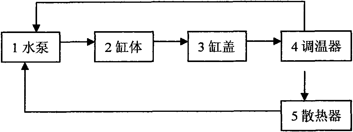
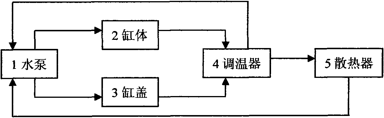
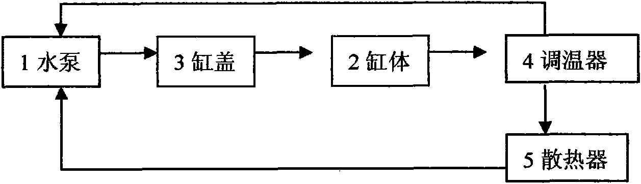
[0016] Figure 4 A visual representation of the water connection of the engine cooling system according to the embodiment of the present invention. When the engine starts, the water pump 1 starts to work, and the coolant is pressurized by the water pump 1 to start circulating. It first flows into the oil cooler 7, and then enters the cylinder head water jacket to cool the key areas of the cylinder head 3. The sheet circulation hole enters the water jacket of the cylinder body to cool the cylinder body 2 and then to the EGR (exhaust gas recirculation) cooler 8. When the temperature is normal, the paraffin in the thermostat 4 is solid, and the two-way water inlet of the radiator 5 In the state where the main valve is closed and the auxiliary valve is open, the main valve of the thermostat 4 is in a closed state, and the coolant from the radiator 5 of the water tank cannot enter the wa...


PUM


Abstract

The invention discloses an engine cooling system and a cooling method. The cooling system comprises a water pump, a double-valve temperature regulator, a machine oil cooler, a water jacket of a cylinder body, a water jacket of a cylinder cover, a water tank radiator and an EGR cooler. The cooling system adopts a water passage circulation as follows: when the engine is started, the water pump begins to work; cooling liquid firstly flows into the machine oil cooler and enters in the water jacket of the cylinder cover to cool the key area of the cylinder cover, and then enters in the water jacket of the cylinder body from a gasket circulating hole of the cylinder cover to cool the cylinder body and the EGR cooler. The cooling liquid in the cooling system firstly cools the cylinder cover to reduce the temperature of the cylinder cover by 10 DEG C to 15 DEG C, enhance aeration efficiency, enlarge air inlet quantity, promote complete combustion, reduce the formation of discharge objects andenhance output efficiency; After cooling the cylinder cover, the cooling liquid enters in the cylinder body for cooling the cylinder body; the higher temperature of the cylinder body can reduce friction, improve fuel efficiency, enhance the output efficiency and reduce peak value pressure and temperature in the cylinder.

Description

technical field [0001] The invention belongs to the field of automobiles and is suitable for a closed forced water-cooled engine cooling system. Background technique [0002] In the existing engine cooling system, the coolant usually enters the cylinder block through the water pump, then enters the thermostat through the cylinder head, circulates through the thermostat, and finally returns to the water pump. For details, see figure 1 ; or the coolant enters the cylinder body and cylinder head water jacket respectively through the water pump, and then circulates through the thermostat, and finally returns to the water pump. For details, see figure 2 . Generally, it is only required that the engine operating temperature should not be overheated or overcooled, but for traditional engine cooling methods, either the temperature of the cylinder head is too high or the temperature of the cylinder block is slightly lower. This not only affects the fuel consumption rate and output...

Claims


Application Information

Patent Timeline
Patent Type & Authority Applications(China)
IPC IPC(8): F01P3/00F01P7/16
Inventor 唐宗春赵前进
Owner CHERY AUTOMOBILE CO LTD
Why Eureka
Try Eureka