Quick insertion clamping frame of concrete blinding and method for clamping concrete blinding

A technology of concrete formwork and clamping frame, which is applied in the field preparation of formwork/formwork/work frame, building components, construction, etc. It can solve the problems of bending deformation, difficulty in cleaning, and dimensional errors, etc., and achieves convenient assembly. Easy handling and high deformation resistance

Inactive Publication Date: 2013-12-25
富于安(福建)环保模版有限公司
View PDF6 Cites 13 Cited by
  • Summary
  • Abstract
  • Description
  • Claims
  • Application Information

AI Technical Summary

Problems solved by technology

[0004] like image 3 As shown, the distance adjustment frame 1', the stopper frame 2' and the guide frame 3' are connected together by bolts. If the bolts are too tight, it will be inconvenient to open and close the clamping frame. If the bolts are tightened Too loose, because the adjustable distance frame 1', the stop frame 2' and the guide frame 3' are made of channel steel respectively, after pouring concrete in the concrete formwork, if figure 2 The connection of A, B, and C shown will be as image 3 As shown, the groove bottoms of the distance-adjusting frame bar 1', the stop frame bar 2' and the guide frame bar 3' are unbalanced in force and will be bent and deformed. First, the concrete formwork will tilt outwards and the shape and size of the formed column will There is a large error. The second is that the joints between the adjacent existing concrete formworks are wide, and the mortar in the concrete formwork will flow out along the joints and flow to the distance-adjusting frame strip 1' and the stop frame strip 2 ' and guide frame bar 3', once condensed it is difficult to clean
[0005] Moreover, since the distance-adjusting frame bar 1', the stop frame bar 2' and the guide frame bar 3' are connected together by bolts, it is difficult to quickly adjust the clamping frame into various specifications and models after the clamping frame is assembled. It is also very inconvenient to separate the roots into one piece. If it is not disassembled into one piece, the clamping frame will take up a lot of space during the handling process, and it is not convenient for transportation.

Method used


Image

  • Quick insertion clamping frame of concrete blinding and method for clamping concrete blinding
  • Quick insertion clamping frame of concrete blinding and method for clamping concrete blinding
  • Quick insertion clamping frame of concrete blinding and method for clamping concrete blinding

Examples


Embodiment Construction

[0044] In order to further explain the technical solution of the present invention, the present invention will be described in detail below through specific examples.

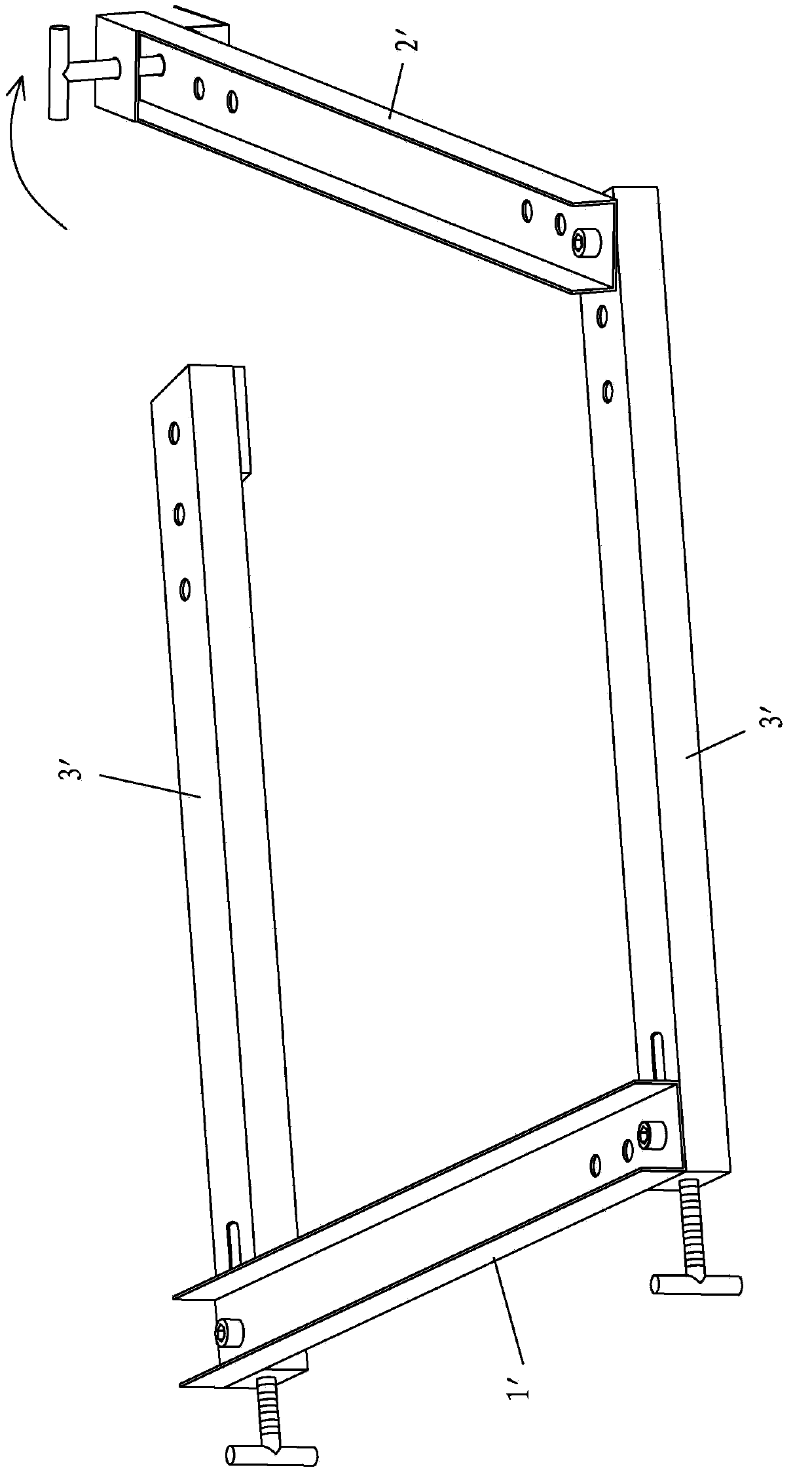
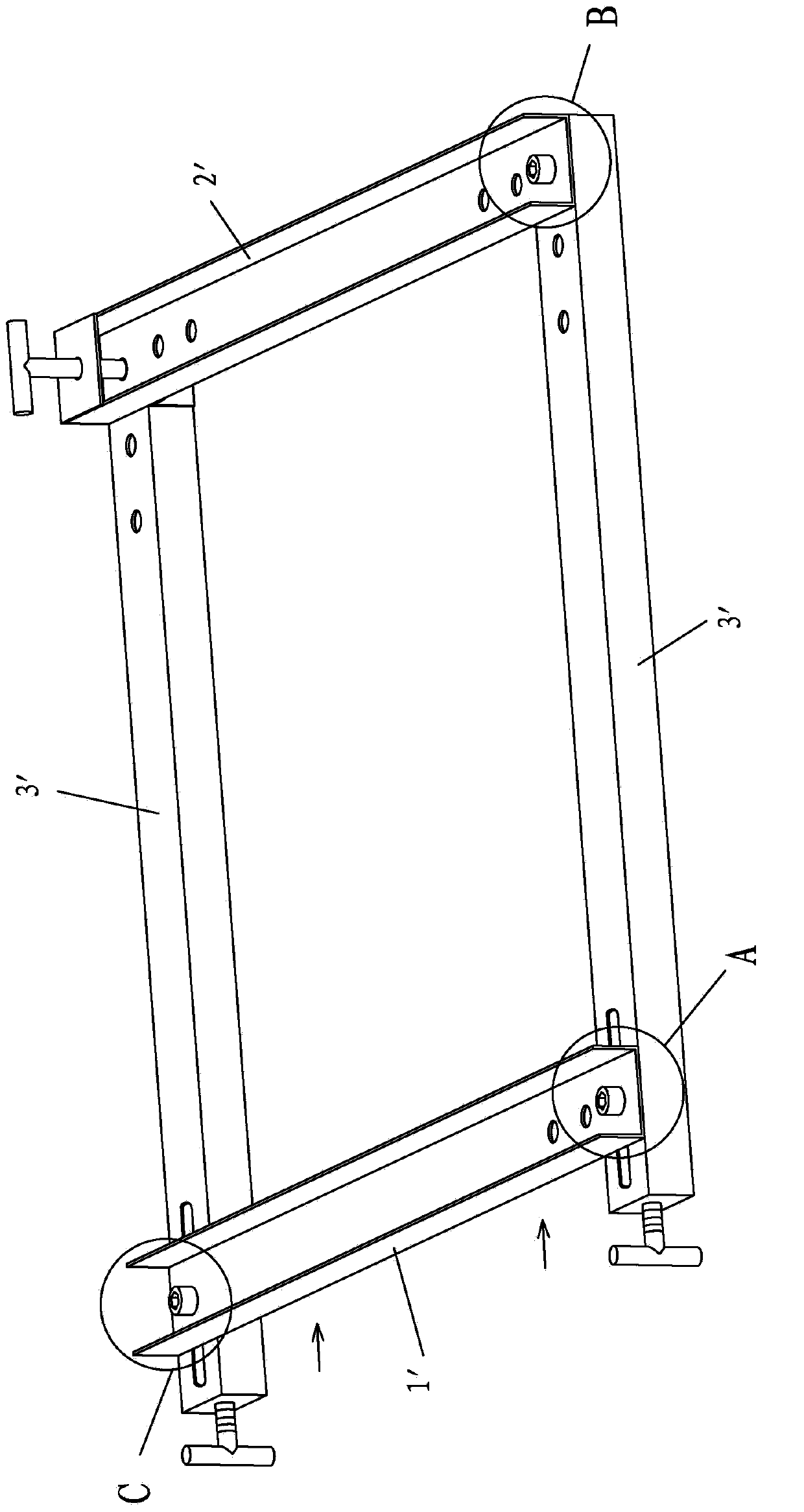
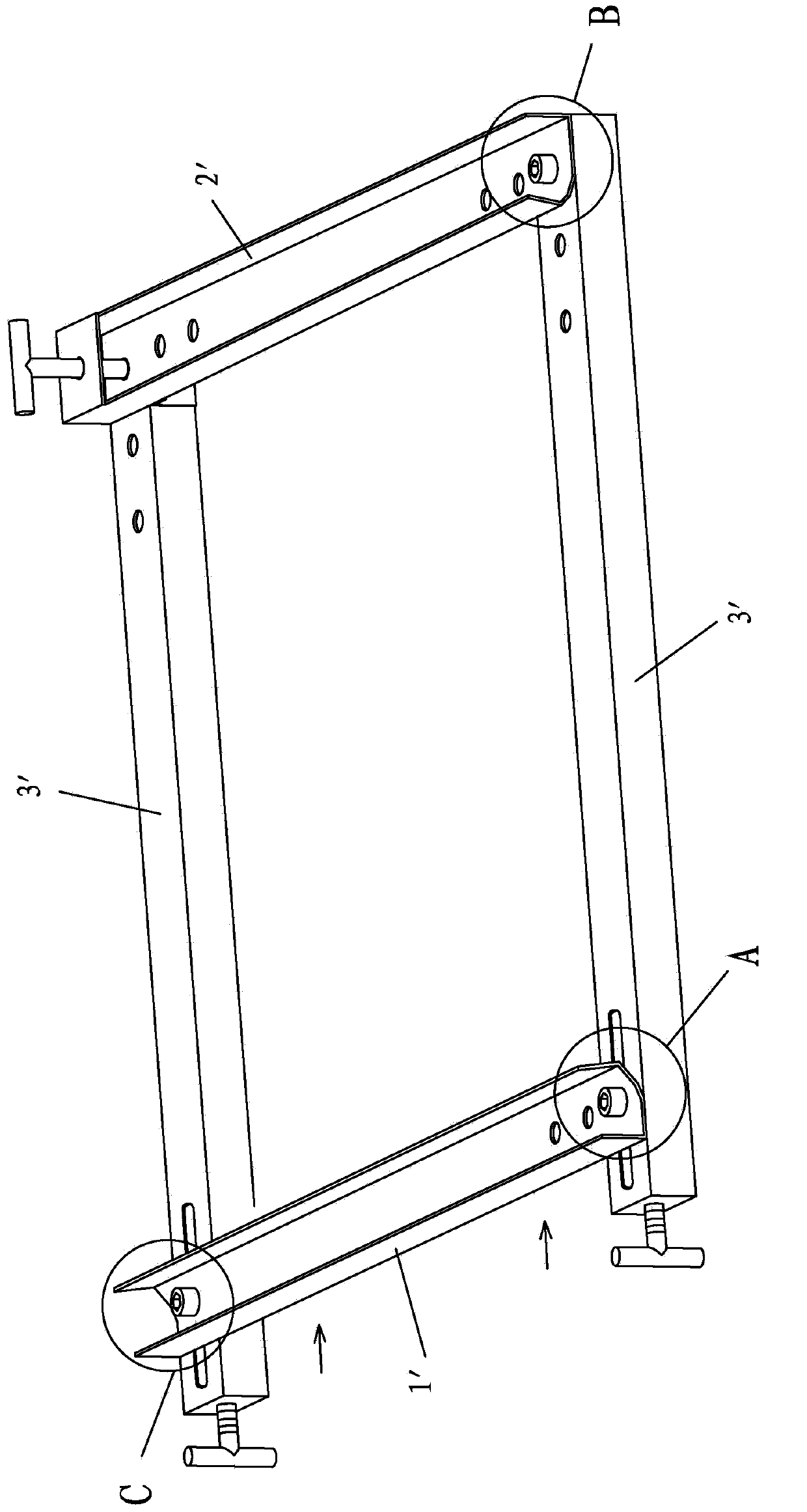
[0045] Such as Figures 4 to 7 As shown, a quick plug-in concrete form clamping frame of the present invention includes a first square pipe 1 , a second square pipe 2 , a third party pipe 3 and a fourth square pipe 4 .

[0046] Both ends of the first square pipe 1 and the third party pipe 3 are respectively provided with jacks 11, 31 for plugging, through which the first square pipe 1, the second square pipe 2, the third party pipe 3 and the fourth square pipe 4 pass. The sockets 11 and 31 are plugged together in turn to form a square frame.

[0047]The jacks 11, 31 at one end of the first square pipe 1 and the third party pipe 3 are respectively multiple, and the multiple jacks 11, 31 are arranged along the length direction of the square pipe respectively, so that they can be quickly plugged into clips of var...


PUM


Abstract

The invention discloses a quick insertion clamping frame of concrete blinding. The clamping frame comprises a first square pipe, a second square pipe, a third square pipe and a fourth square pipe which are inserted and connected together in sequence to form a square frame shape. The invention further discloses a method for clamping the concrete blinding with the above clamping frame. Since the first square pipe, the second square pipe, the third square pipe and the fourth square pipe are mutually inserted and connected together to form the square frame, the clamping frame is convenient and quick in dismounting and mounting. The clamping frame can be dismounted to be pieces when not in use, so the clamping frame does not occupy large space and is convenient to carry, and square pipe structure is higher than a U-steel in non-deformability. The square pipes are mutually inserted and connected during pouring and do not bend and distort due to pressing of mortar in the concrete blinding. The concrete blinding do not incline outwardly, shape and size of a post formed by pouring is close to a set size, and furthermore, piecing clearances between neighboring concrete blinding do not crack too much, the mortar in the concrete blinding does not flow out along the piecing clearances, and accordingly trouble of cleaning the mortar is omitted.

Description

technical field [0001] The invention relates to a concrete template clamping frame. Background technique [0002] Such as figure 1 with figure 2 As shown, when pouring a column, it is necessary to fix the concrete formwork that forms the shape of the column. For this reason, the applicant applied for "a concrete formwork clamping frame", which includes the distance-adjustable frame bar 1' and the stop frame set opposite to each other. Bar 2', and two guide frame bars 3' that are arranged oppositely; Adjustable distance frame bar 1', a guide frame bar 3', stop frame bar 2' and another guide frame bar 3' to expand and The mode of reducing the area enclosed by the clamping frame is connected together from end to end in sequence. [0003] Since the adjustable distance frame bar 1', the guide frame bar 3', the stop frame bar 2' and the other guide frame bar 3' are connected together end to end in order to form a frame shape, the clamping frame is directly placed in the enclos...

Claims


Application Information

Patent Timeline
Patent Type & Authority Applications(China)
IPC IPC(8): E04G13/02
Inventor 许金锔吴清瑶
Owner 富于安(福建)环保模版有限公司
Why Eureka
Try Eureka