Heavily loaded silent hinge

A heavy-duty, quiet technology, applied in the field of hinges, can solve the problems of reducing the life of the hinge, producing loud noise, and large frictional resistance, and achieving the effect of compact and reasonable hinge structure, improved muteness, and low frictional resistance.

Active Publication Date: 2013-12-25
SUGATSUNE IND CO LTD
View PDF5 Cites 0 Cited by
  • Summary
  • Abstract
  • Description
  • Claims
  • Application Information

AI Technical Summary

Problems solved by technology

However, during the opening or closing process of the existing hinges, due to the relatively large frictional resistance between the rotating parts (connecting rods, crankshafts, etc.) On the other hand, the noise when opening and closing the door is louder, and the hinge holes of the rotating parts are also worn faster, which reduces the life of the hinge

Method used


Image

  • Heavily loaded silent hinge
  • Heavily loaded silent hinge
  • Heavily loaded silent hinge

Examples


Embodiment 1

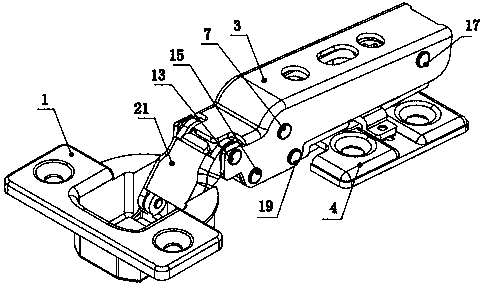
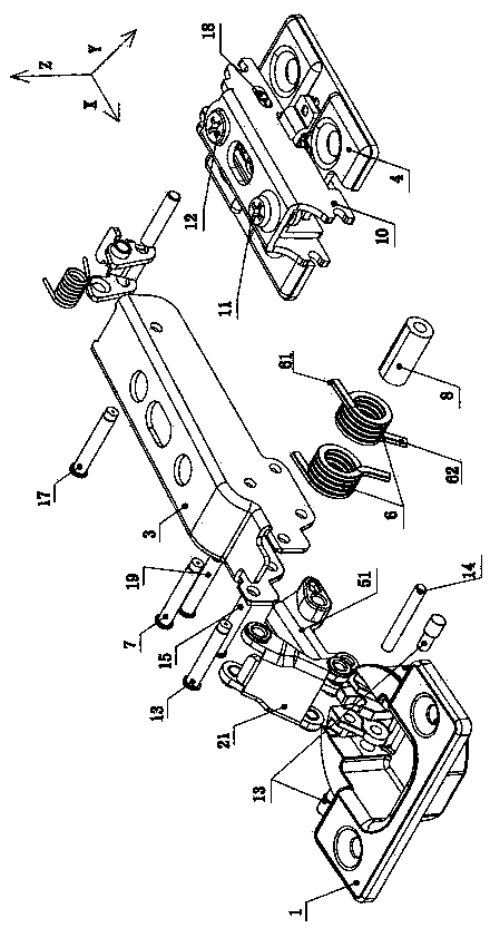
[0029] The structure of the heavy-duty silent hinge of the present invention is as follows: figure 1 , 2 , 3, 4, 9, including the hinge cup 1, the connecting rod assembly 2, the hinge arm 3, the base 4, the crankshaft assembly 5, the fixed arm 10, the moving arm 16 and the elastic member 6 that makes the hinge cup 1 have closing force , The elastic member 6 of this embodiment is a torsion spring. The hinge arm 3 is placed above the base 4, the fixed arm 10 and the movable arm 16 are placed between the base 4 and the hinge arm 3, and the fixed arm 10 is located below the movable arm 16. The arm 16 is connected so that the hinge arm 3 will not move along the X-axis direction relative to the movable arm 16. The movable arm 16 is connected with the fixed arm 10 through the connecting shaft 18, and the connecting shaft 18 passes through the hole 41 on the base 4 to connect the base 4 Connected with the fixed arm 10, the movable arm 16 drives the hinge arm 3 to move along the X-ax...

Embodiment 2

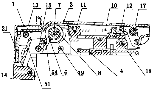
[0036] The structure of the heavy-duty silent hinge of this embodiment is similar to that of Embodiment 1. One of the differences is that the above-mentioned crankshaft assembly 5 is composed of a crankshaft 51, a crankshaft bushing 52, and a crankshaft fixing bushing 53. Compared with Embodiment 1, the torque is reduced. The spring retainer 54 and the fixed shaft 55, the first and second protruding ends 61, 62 of the torsion spring are respectively pressed on the hinge arm 3 and the crankshaft 51; the second difference: the first protrusion 911 and the first groove 912 The set positions are exchanged, the positions set by the second protrusion 921 and the second groove 922 are exchanged, that is, the first groove 912 is set on the outer side wall of the connecting rod sleeve 22, and the first protrusion 911 is set On the hole wall of the first hinge hole 211 ; the second groove 922 is set on the outer wall of the crankshaft sleeve 52 , and the second protrusion 921 is set on t...


PUM


Abstract

The invention relates to a heavily loaded silent hinge which comprises a hinge cup, a connecting rod assembly, a hinge arm, a base, a crankshaft assembly and an elastic part. The hinge cup has closing force by the aid of the elastic part, the hinge arm is adjustably mounted on the base, the connecting rod assembly comprises a connecting rod and connecting rod shaft sleeves, one end of the connecting rod is hinged to the hinge cup, the other end of the connecting rod is hinged to the hinge arm, and the connecting rod shaft sleeves are sleeved in first hinge holes in two ends of the connecting rod respectively. The crankshaft assembly comprises a crankshaft, a crankshaft sleeve and a crankshaft fixing shaft sleeve, one end of the crankshaft is hinged to the hinge cup, the other end of the crankshaft is hinged to the hinge arm, the crankshaft sleeve is sleeved in a second hinge hole of the crankshaft correspondingly hinged to the hinge cup, the crankshaft fixing shaft sleeve is sleeved in a third hinge hole of the crankshaft correspondingly hinged to the hinge arm, and the hinge cup drives the crankshaft and connecting rod to rotate in the door opening and closing process, so that a door is opened and closed. As the shaft sleeves are sleeved in the hinge holes of the crankshaft and the connecting rod, frictional resistance is low in the transmission process, and silence is achieved.

Description

technical field [0001] The invention relates to a hinge, in particular to a heavy-duty silent hinge for furniture doors, which belongs to the improvement technology of the hinge. Background technique [0002] At present, the furniture industry generally uses hinges to connect cabinet doors when manufacturing furniture. This kind of door hinge is equipped with a spring device, which makes the door have a compressive force when opening and closing the door, eliminating the need for magnetic attraction or bolt fixing in the past. Easy to use without hassle. However, during the opening or closing process of the existing hinges, due to the relatively large frictional resistance between the rotating parts (connecting rods, crankshafts, etc.) In addition, the noise when opening and closing the door is louder, and the hinge holes of the rotating parts wear faster, which reduces the life of the hinge. Contents of the invention [0003] The object of the present invention is to pr...

Claims


Application Information

Patent Timeline
IPC IPC(8): E05D3/06E05D5/00
Inventor 戴贵阳
Owner SUGATSUNE IND CO LTD
Why Eureka
Try Eureka