
Cylinder sleeve cooling structure of engine

A technology of engine cylinder and cooling structure, which is applied to engine components, machines/engines, cylinders, etc., can solve the problems of piston ablation, high cylinder liner temperature, and difficult control of cooling water flow state, so as to reduce the failure of parts and components. risk, improve the effect of local high temperature, improve the uniformity of water flow

Inactive Publication Date: 2013-12-25
CHINA NORTH ENGINE INST TIANJIN
View PDF3 Cites 2 Cited by
  • Summary
  • Abstract
  • Description
  • Claims
  • Application Information

AI Technical Summary

Problems solved by technology

However, the flow state of the cooling water outside the cylinder liner in the traditional design is not easy to control, and the water flow is slow in some areas of the water chamber, commonly known as "dead zone". The temperature in the area is higher
When the engine heat load is low, the high local temperature of the cylinder liner will not cause reliability problems, but when the engine heat load is high, the high local temperature of the cylinder liner will cause many reliability problems, such as piston ablation, pulling How to optimize the flow of cooling water to ensure that the temperature distribution of the cylinder liner is as uniform as possible becomes a problem that needs special consideration.

Method used


Image

  • Cylinder sleeve cooling structure of engine
  • Cylinder sleeve cooling structure of engine
  • Cylinder sleeve cooling structure of engine

Examples


Embodiment Construction

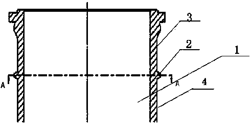
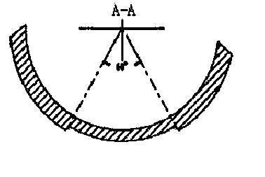
[0012] Such as figure 1 , figure 2 Shown, a kind of cooling structure of engine cylinder liner, it comprises cylinder liner 1 and the water flow guiding rib 2 that is arranged on cylinder liner 1, it is characterized in that cylinder liner 1 is an annular water chamber outside, and water flow guiding rib 2 guides said annular The water cavity is divided into the upper part 3 of the annular water cavity and the lower part 4 of the annular water cavity. The water flow guide rib 2 is a partially raised rib plate structure, and a gap is designed to guide the flow of cooling water at a position away from the water inlet and return ports.

[0013] The water flow guiding rib 2 is designed with a notch with a central angle of 60 degrees at a position away from the water inlet and return ports.

[0014] The structure of the water flow guide rib 2 is spiral.

[0015] The structure of the water flow guide rib 2 is a multi-layer structure.

[0016] The working principle is as follows:...


PUM


Abstract

The invention relates to a cylinder sleeve cooling structure of an engine. The cylinder sleeve cooling structure of the engine comprises a cylinder sleeve (1) and water flow guide ribs (2). The water flow guide ribs (2) are arranged on the cylinder sleeve (1). The cylinder sleeve cooling structure of the engine is characterized in that the annular water chamber is formed outside the cylinder sleeve (1); the annular water chamber is divided into the annular water chamber upper portion (3) and the annular water chamber lower portion (4) through the water flow guide ribs (2) which are of rib plate structures which protrude locally; a gap which is used for guiding circulation of cooling water is formed at the position far away from the water inlet and the water return opening. According to the cylinder sleeve cooling structure of the engine, a flow path of the cooling water is greatly extended, the uniformity of water flow in the annular chamber is improved, and the risk of component failure of the cylinder sleeve due to the too high local temperature is reduced.

Description

technical field [0001] The invention belongs to the field of engines, and in particular relates to an engine cylinder liner cooling structure. Background technique [0002] In the common engine structure design, when the wet cylinder liner is used, cooling water needs to be arranged outside the cylinder liner in the working state to take away the heat generated by fuel combustion and reduce the temperature of the cylinder liner, cylinder head and piston. The outer water cavity of the cylinder liner is generally designed as a circular rotary structure. The advantage of this design is that the manufacturing process is better and the deformation of the cylinder liner is easy to control. However, the flow state of the cooling water outside the cylinder liner in the traditional design is not easy to control, and the water flow is slow in some areas of the water chamber, commonly known as "dead zone". The temperature in the area is higher. When the engine heat load is low, the h...

Claims


Application Information

Patent Timeline
Patent Type & Authority Applications(China)
IPC IPC(8): F02F1/10
Inventor 姚亮宇王家雄郭昌明张小良曾壮黄树和王龙飞尹玉婷
Owner CHINA NORTH ENGINE INST TIANJIN
Learn More