Closed cold pool system

A cold pool, closed cooling technology, applied in cooling/ventilation/heating renovation, modification of standard racks/cabinet, electrical components, etc., can solve the problems of closed transmission equipment, reduce maintenance costs, improve local cooling efficiency, low impact effect

Active Publication Date: 2020-03-27
ZTE CORP
View PDF3 Cites 7 Cited by
  • Summary
  • Abstract
  • Description
  • Claims
  • Application Information

AI Technical Summary

Problems solved by technology

[0003] The main purpose of the embodiment of the present invention is to propose a closed cold pool system and its interaction method, aiming to solve the problem of how to close the cold pool for the transmission equipment of complex air ducts

Method used


Image

  • Closed cold pool system
  • Closed cold pool system
  • Closed cold pool system

Examples


Embodiment 1

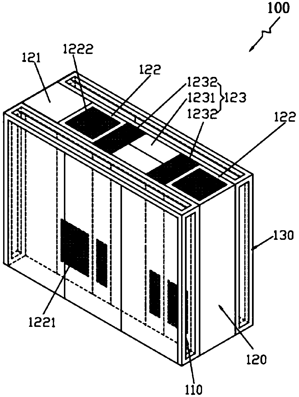
[0016] Such as figure 1 As shown, this embodiment provides a closed cold pool system 100 , and the closed cold pool system 100 includes a first closed assembly 110 , a cabinet assembly 120 and a second closed assembly 130 . Wherein, the first closed component 110 is disposed on the front side of the cabinet component 120, so that the front side of the cabinet component 120 forms a first closed cold aisle. The second closed assembly 130 is arranged on the rear side of the cabinet assembly, so that the rear side of the cabinet assembly 120 forms a second closed cold aisle. The room air conditioner 122 includes a front air supply port 1221, a rear air supply port (not shown) and a top air return port 1222. The front air supply port 1221 is connected to the first closed cold aisle, and the rear air supply port is connected to the second closed cold aisle. The main equipment unit 123 It is a structure with front and rear air inlets and top air outlets formed by the combination of ...

Embodiment 2

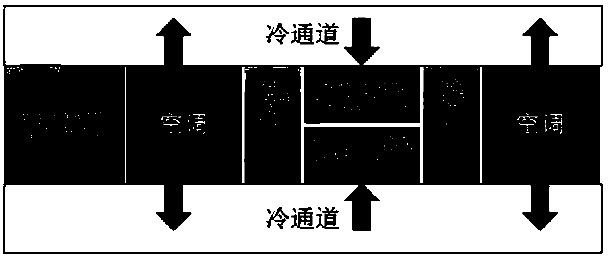
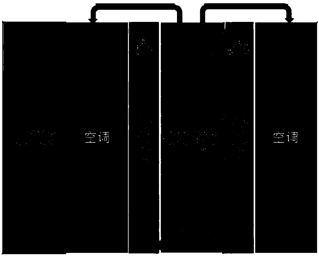
[0023] Such as Figure 6 As shown, Embodiment 2 of the present invention proposes a closed cold pool system. The difference between the closed cold pool system and the closed cold pool system 100 in Embodiment 1 is that the cabinet assembly includes a power distribution cabinet and a main cabinet group. The main cabinet The lease includes two main equipment units and three inter-row air conditioners, one main equipment unit is set between two inter-row air conditioners, and the power distribution cabinet is installed at any end of the main cabinet group. The airflow direction during normal operation is basically the same as the airflow direction of the closed cold pool system 100 in the first embodiment.

[0024]It can be seen that according to the configuration requirements of the actual computer room, the closed cold pool can seal multiple main equipment units. At this time, the cabinet components include the main cabinet group and the power distribution cabinet, and the mai...


PUM


Abstract

The invention discloses a sealing cold pool system, and belongs to the technical field of heat dissipation protection of transmission equipment in a communication machine room. The system comprises afirst sealing assembly, a cabinet assembly and a second sealing assembly. The first sealing assembly is arranged on the front side of the cabinet assembly to form a first sealing cold channel. The second sealing assembly is arranged at the rear side of the cabinet assembly to form a second sealing cold channel; the cabinet assembly comprises a power distribution cabinet, an inter-column air conditioner and a main equipment unit which are arranged side by side. The inter-column air conditioner comprises a front air supply port, a rear air supply port and a top air return port, the front air supply port is communicated with the first sealing cold channel, the rear air supply port is communicated with the second sealing cold channel, and the main equipment unit is of a front-rear air inlet and top air outlet structure formed by combining a plurality of transmission equipment and air guide cabinets on the two sides of the transmission equipment. According to the technical scheme, cold poolsealing is carried out on transmission equipment with a complex air duct, the heat dissipation problem of high-power-consumption transmission equipment is solved, the local refrigeration efficiency of a machine room is improved, and the maintenance cost of the machine room is reduced.

Description

technical field [0001] The invention relates to the technical field of heat dissipation protection for transmission equipment in a communication machine room, in particular to a closed cold pool system. Background technique [0002] With the increase in the integration of communication equipment, the power consumption of a single cabinet increases year by year, and the power consumption of a single cabinet has far exceeded the cooling capacity of a single rack in the computer room. Heat dissipation problems such as local hot spots are formed. The heat dissipation problem of the equipment in the computer room is especially prominent in the transmission equipment with complex air ducts. The ventilation mode of the highly integrated transmission equipment on the market is front-to-back air intake, front-to-back upper air outlet, or front-to-back air intake, and upper air outlet. form. In order to solve the heat dissipation problem of such high-power transmission equipment, it...

Claims


Application Information

Patent Timeline
Patent Type & Authority Applications(China)
IPC IPC(8): H05K7/20
CPCH05K7/2069H05K7/2059H05K7/20145H05K7/20754
Inventor 刘帆
Owner ZTE CORP
Why Eureka
Try Eureka