Solar auxiliary heat-pump drying system

A solar energy and heat pump technology, applied in drying solid materials, drying gas layout, drying and other directions, can solve the problems of high energy consumption and low COP of heat pump system

Inactive Publication Date: 2013-12-25
HUNAN UNIV OF SCI & TECH
View PDF6 Cites 8 Cited by
  • Summary
  • Abstract
  • Description
  • Claims
  • Application Information

AI Technical Summary

Problems solved by technology

[0004] The purpose of the present invention is to solve the problems of high energy consumption and low COP of the traditional heat pump drying system, and provide a s

Method used


Image

  • Solar auxiliary heat-pump drying system
  • Solar auxiliary heat-pump drying system
  • Solar auxiliary heat-pump drying system

Examples


Embodiment Construction

[0016] The present invention will be further described in detail below in conjunction with the accompanying drawings and embodiments.

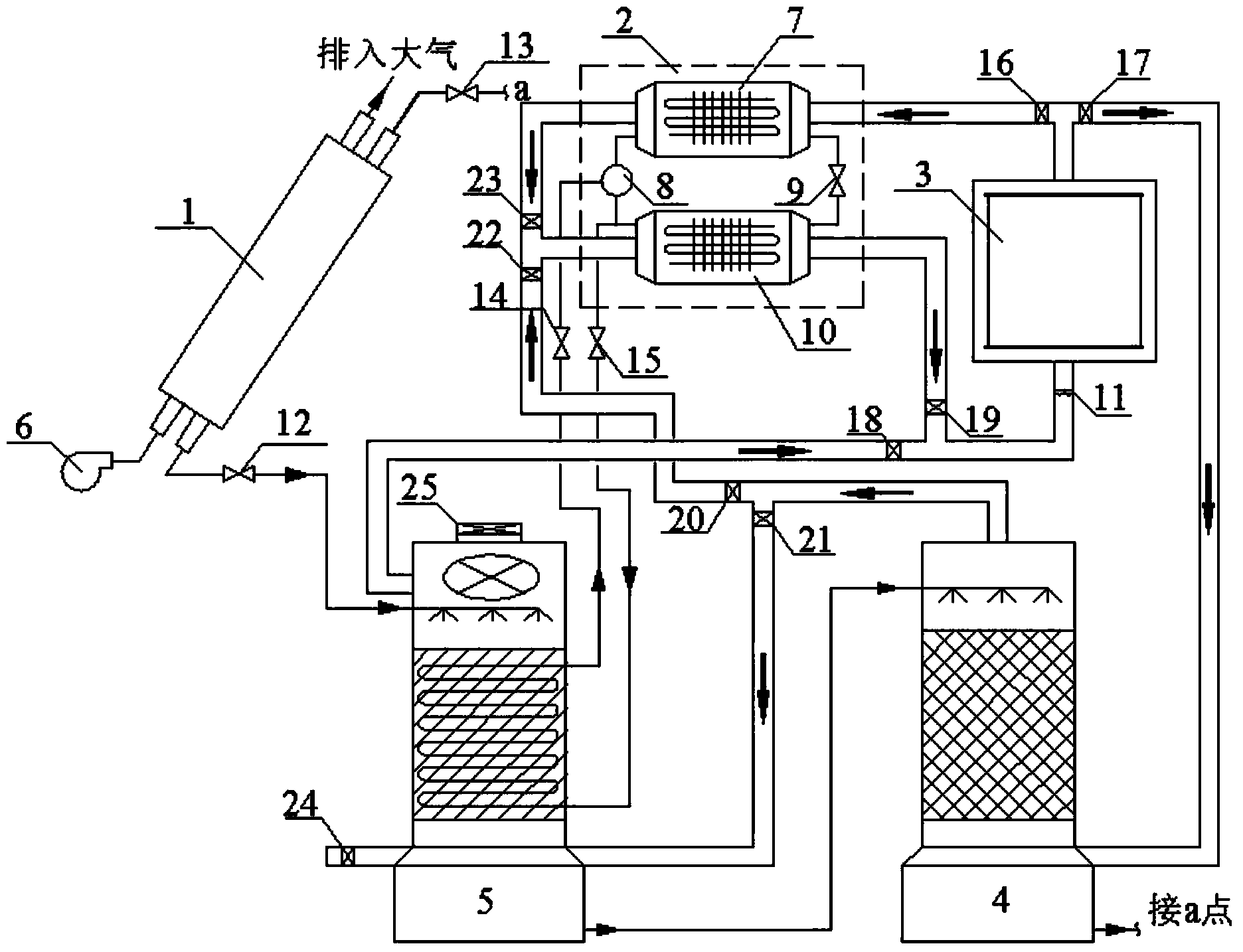
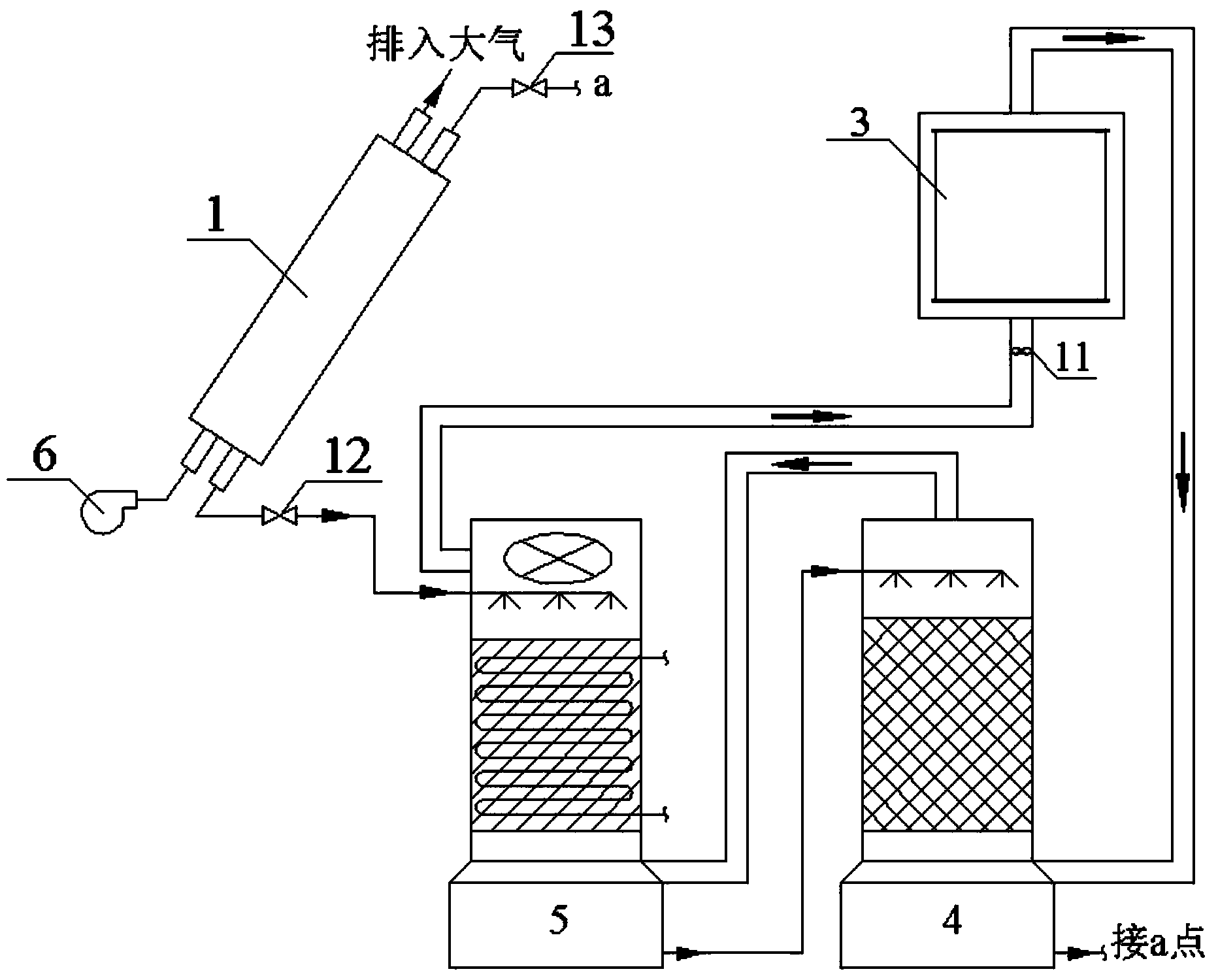
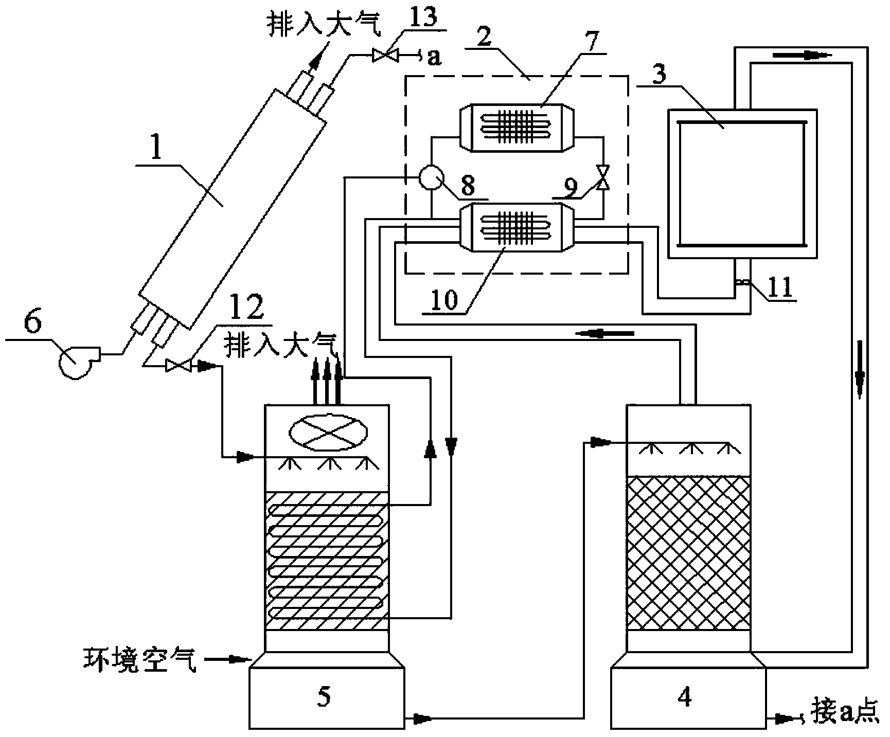
[0017] see figure 1 , the present embodiment includes a drying chamber 3, a heat pump 2 connected between the air outlet and the air inlet of the drying chamber 3 through an air duct; the heat pump 2 includes an evaporator 7, a condenser 10, a compressor 8 and a throttling device 9, The air inlet of the drying chamber 3 is equipped with a blower fan 11 . From figure 1 It can be seen in the figure that it also includes a solar solution regenerator 1 , an internal heat / adiabatic packed tower 5 and an adiabatic packed tower 4 . The solution outlet of the solar solution regenerator 1 is sequentially connected in series with the internal heat / insulation dual-purpose packed tower 5 and the adiabatic packed tower 4 through the solution pipeline, and the solution outlet of the adiabatic packed tower 4 is connected with the solution inlet a of the so...


PUM


Abstract

The invention discloses a solar auxiliary heat-pump drying system. The solar auxiliary heat-pump drying system comprises a drying chamber and a heat pump and also comprises a solar solution regenerator, an internal-heat/heat-insulating dual-purpose packing tower and a heat-insulating packing tower. The solar auxiliary heat-pump drying system disclosed by the invention has the advantages that the solar energy can be fully utilized in different seasons of the whole year, the dehumidified dilute solution is heated and regenerated by utilizing the solar energy under the condition of sufficient solar energy, and the heat pump and the solar energy are utilized for realizing the dehumidifying and heating process to the air when the solar energy is insufficient, so that high-efficiency and stable operation of the system can be ensured; when a solution dehumidifying mode is adopted, the solution is directly contacted with the air, heat-exchange temperature difference is low, the irreversible loss is less, and the problem of larger energy consumption in the traditional condensed dehumidifying mode can be solved; and simultaneously, the solution regenerating heat and a part of heat for heating the air are from the solar energy, and can be utilized freely, so that the energy-saving effect of the system is obvious in the whole-year operation.

Description

technical field [0001] The invention belongs to the technical field of drying systems, and in particular relates to a solar-assisted heat pump drying system utilizing solution dehumidification / heating technology. Background technique [0002] Since the heat pump dryer can effectively recover and utilize the heat in the air, it is more and more widely used. The humidity of the air after drying the material in the heat pump dryer drying room is high. The traditional heat pump dryer adopts the method of condensation dehumidification to dehumidify the air: the humid air coming out of the drying room first passes through the heat pump evaporator to reduce the air temperature to the dew point. Water vapor is precipitated below the temperature, and then the dehumidified dry air is heated up through the heat pump condenser, and finally sent to the drying room to dry the material. In this way, the humid air needs to be cooled by the evaporator first, and then heated by the condenser...

Claims


Application Information

Patent Timeline
IPC IPC(8): F26B21/04F26B25/00
Inventor 李永存熊慧灵高旭林爱晖邹声华王海桥王卫军刘荣华刘何青
Owner HUNAN UNIV OF SCI & TECH
Why Eureka
Try Eureka