
A Microstrip Antenna

A microstrip antenna and microstrip technology, applied in antennas, antenna arrays, radiating element structures, etc., can solve the problems of thick thickness, large radiating element area, and unsatisfactory problems, so as to improve the cross-polarization suppression ratio and increase external Radiation window, effect of improving polarization purity

Active Publication Date: 2016-03-30
HUAWEI TECH CO LTD
View PDF2 Cites 0 Cited by
  • Summary
  • Abstract
  • Description
  • Claims
  • Application Information

AI Technical Summary

Problems solved by technology

[0004] In view of the above requirements, the radiating element mainly used in the existing microstrip antenna is a double-layer square or circular patch antenna; the biggest problem with the simple double-layer square or circular patch is that the cross-polarization suppression ratio is not ideal , the typical value of a single radiating unit is between 10-15dBc, which does not meet the isolation requirements of polarization MIMO (Multi-inputMulti-output, multiple input and multiple output); at the same time, the existing microstrip antenna radiating unit adopts square stickers Chip time, in order to meet the requirements of mobile communication base station equipment for antennas, its size is generally more than 58mm×58mm, and its height is more than 8mm. The radiation unit has a large area and a thick thickness, which is not conducive to the needs of product miniaturization design.

Method used


Image

  • A Microstrip Antenna
  • A Microstrip Antenna
  • A Microstrip Antenna

Examples


Embodiment Construction

[0030] The following will clearly and completely describe the technical solutions in the embodiments of the present invention with reference to the accompanying drawings in the embodiments of the present invention. Obviously, the described embodiments are only some, not all, embodiments of the present invention. Based on the embodiments of the present invention, all other embodiments obtained by persons of ordinary skill in the art without making creative efforts belong to the protection scope of the present invention.

[0031] In describing the present invention, it is to be understood that the terms "center", "upper", "lower", "front", "rear", "left", "right", "vertical", "horizontal", The orientations or positional relationships indicated by "top", "bottom", "inner", "outer", etc. are based on the orientations or positional relationships shown in the drawings, and are only for the convenience of describing the present invention and simplifying the description, rather than in...


PUM


Abstract

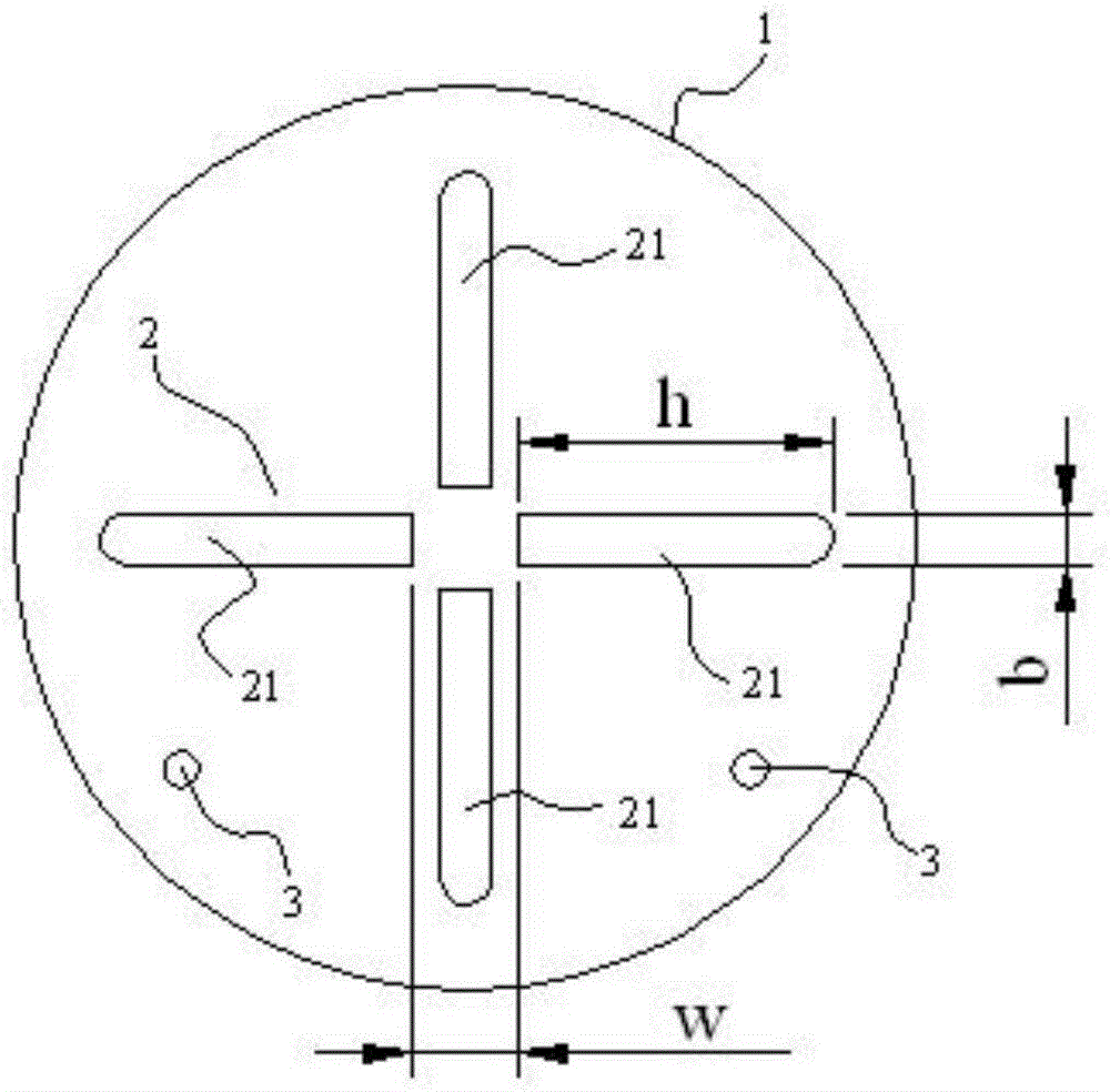
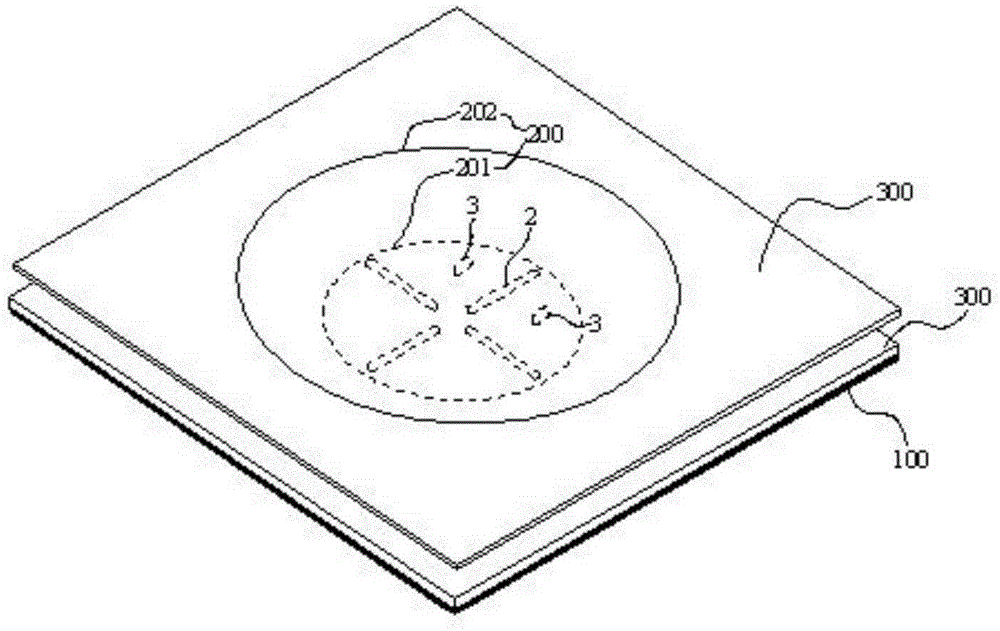
The invention discloses a radiation patch for a microstrip antenna and the microstrip antenna and relates to the technical field of antennas. The radiation patch for the microstrip antenna and the microstrip antenna aim at solving the problems that broadband-orientation and miniaturization of an existing microstrip antenna can not be achieved and the cross polarization rejection ratio is not ideal. Cross-shaped grooves are formed in the radiation patch for the microstrip antenna and comprise at least four long sealing grooves arranged in a cross shape. The long sealing grooves are not communicated with one another. The radiation patch for the microstrip antenna and the microstrip antenna are used for design of antennas of a mobile communication base station.

Description

technical field [0001] The invention relates to the technical field of antennas, in particular to a radiation patch for a microstrip antenna and a microstrip antenna. Background technique [0002] Microstrip antenna has the advantages of low thickness, simple structure and good processability, so it has been widely used. Microstrip antennas include many structural forms. From the perspective of the composition of microstrip antennas, microstrip antennas include three basic components, namely the radiation unit, reference ground, and feed structure. [0003] The application scenario targeted by the solution of the present invention is a wireless cellular communication single-band low-profile microstrip antenna; the working frequency is around 2 GHz, and the antenna thickness is less than 10 mm from the top of the radiation unit to the reference ground. [0004] In view of the above requirements, the radiating element mainly used in the existing microstrip antenna is a double...

Claims


Application Information

Patent Timeline
Patent Type & Authority Patents(China)
IPC IPC(8): H01Q1/36H01Q1/38H01Q13/08H01Q21/00
Inventor 罗兵杨仕文朱全江
Owner HUAWEI TECH CO LTD
Learn More