

Rotary chair leg and stand bars thereof
A technology of swivel chair feet and support feet, which is applied in the field of office chairs and swivel chairs, and can solve the problems of large molds, large space occupation, and high transportation costs
- Summary
- Abstract
- Description
- Claims
- Application Information
AI Technical Summary
Problems solved by technology
Method used
Image

Examples
Embodiment 1
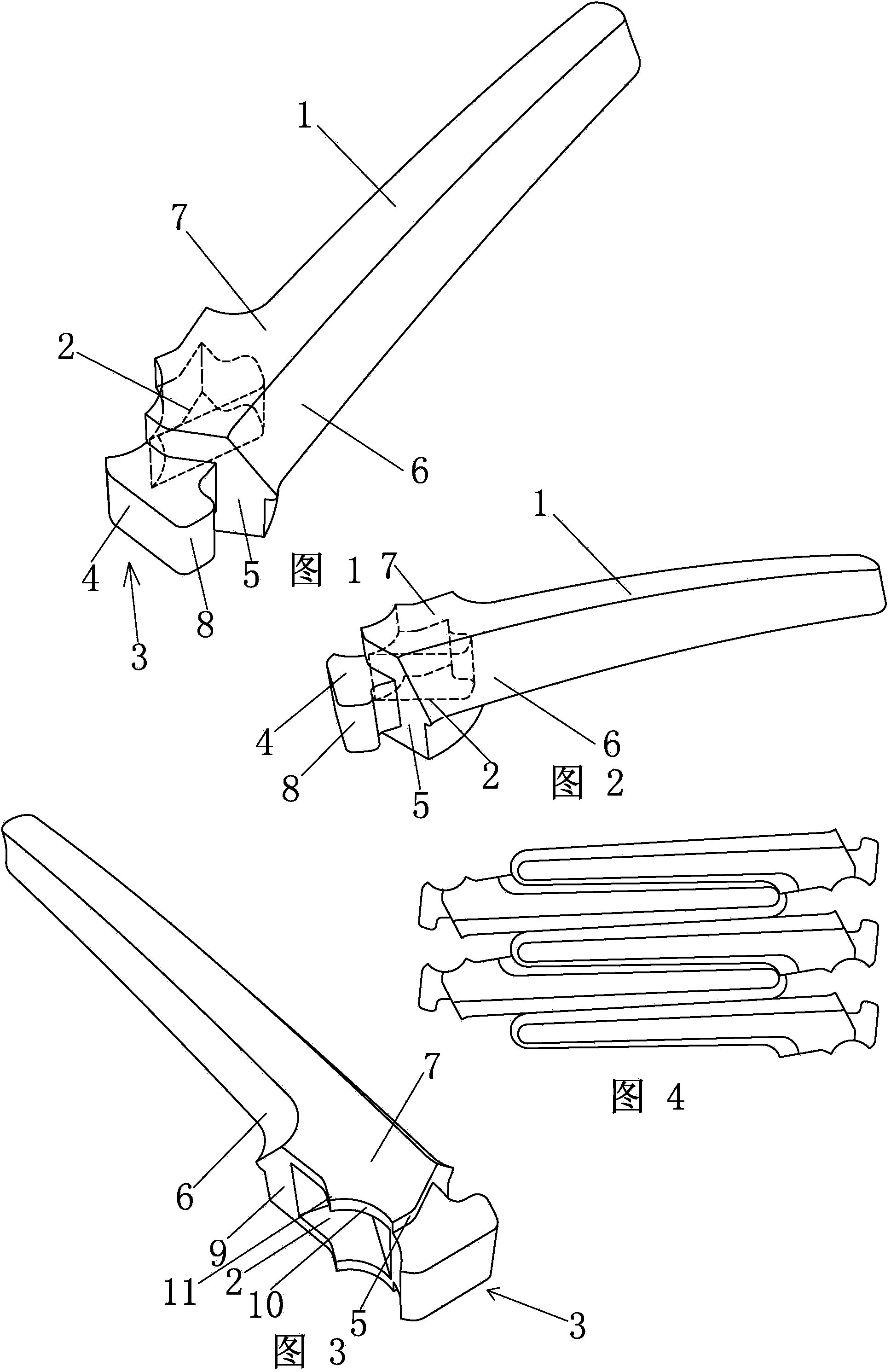
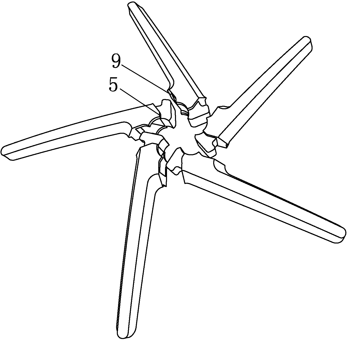
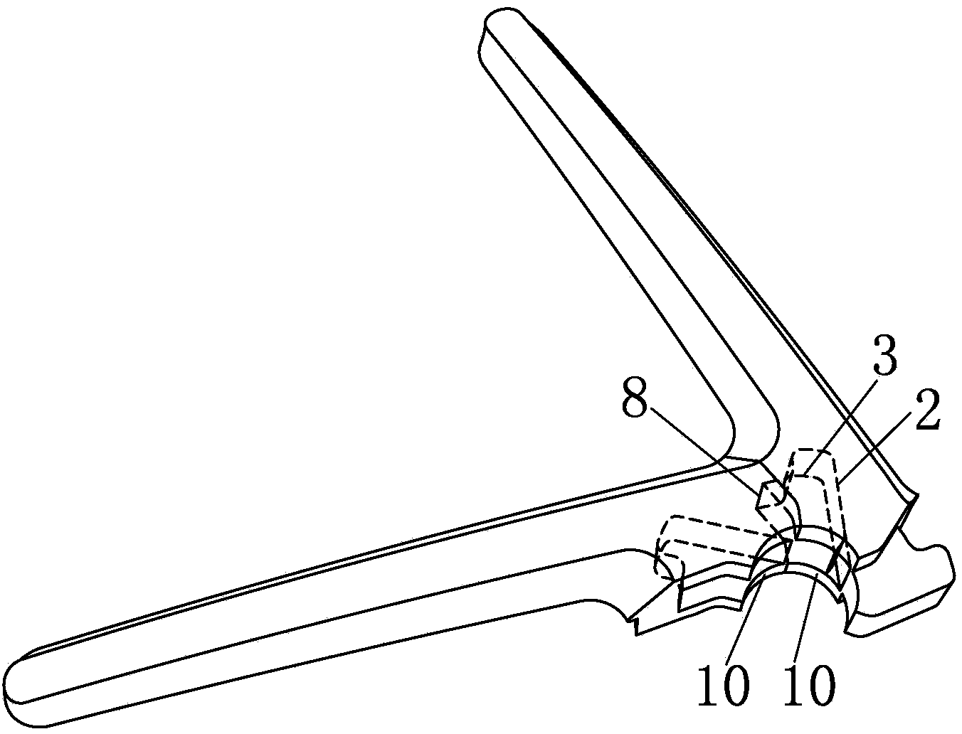
[0035] Embodiment 1: a kind of supporting foot of swivel chair foot, as Figure 1~3 As shown, in order to better describe the present invention, when the leg 1 is in normal use as a reference, the bottom of one end of the leg 1 is provided with a roller mounting hole (not shown), and the other end of the leg 1 has two sides 6, A top surface 7, a bottom surface and a front end surface 5, wherein, such as Figure 1~2 As shown by the dotted line, a buckle groove 2 is provided on one of the side surfaces 6 of the other end of the leg 1 , and a buckle hook 3 matching the buckle groove 2 is provided on the front end surface 5 of this end.
[0036] Specifically, the buckle hook 3 includes a buckle tongue 4, one end of the buckle tongue 4 is connected to the front end surface 5 of the other end of the leg, and the other end of the buckle tongue 4 is extended toward a direction away from the buckle groove 2 with a hook 8, The hook 8 extends along the width of the leg 1 .
[0037] The...
Embodiment 2
[0041] Embodiment 2: This embodiment is also provided with structures such as buckle grooves and buckle hooks as in Embodiment 1, but compared with Embodiment 1, a more specific form is provided, such as Figures 11 to 13 As shown, in actual production, the supporting foot is in a hollow state, which can be provided with one or more interlayers 14, and reinforcing ribs are arranged in the interlayer 14 to improve the strength of the supporting foot.
[0042] Such as Figures 14 to 16As shown, after the leg is assembled into a swivel chair foot, a sleeve 15 is inserted in the center hole. The sleeve 15 is hollow and has openings at both ends. The upper end of the sleeve 15 is provided with a flange extending outward along the radial direction of the sleeve 15. 16. The flange 16 overlaps the periphery of the central hole. The purpose of setting the sleeve pipe 15 is to prop up the spliced swivel chair legs, and then insert the gas rod into the sleeve pipe 15 and get final pro...
PUM
 Abstract
Description
Claims
Application Information