
Cyclic continuous degassing device

A technology of degassing device and degassing tank, which is applied in the directions of liquid degassing, chemical instruments and methods, separation methods, etc., can solve the problems of affecting the flow rate of the circulating system, excessive degassing, and cavitation of the circulating pump, so as to improve the degassing. Efficiency, prolong service life, avoid the effect of repeated starts

Active Publication Date: 2015-11-18
广东博思杜尔实业有限公司
View PDF5 Cites 0 Cited by
  • Summary
  • Abstract
  • Description
  • Claims
  • Application Information

AI Technical Summary

Problems solved by technology

[0004] The continuous degassing device with this structure has greatly improved the efficiency of liquid degassing, but it has the following disadvantages: 1) The degassing quality is unstable; 2) The fine filter is easy to block, which affects the flow rate of the circulation system. The change affects the liquid level of the liquid in the degassing tank, which further causes the circulating pump to start frequently. Therefore, the flow regulating gate valve must be adjusted frequently to prevent the frequent stop of the circulating pump caused by the low liquid level; 3) The vacuum degree of the vacuum generator cannot be adjusted, which is easy Excessive degassing occurs, causing cavitation to the circulating pump and affecting the life of the circulating pump; 4) The position of the liquid return port of the liquid storage tank is relatively low, which is easy to cause the occurrence of liquid backflow

Method used


Image

  • Cyclic continuous degassing device

Examples


Embodiment Construction

[0017] The present invention will be further described in detail below in conjunction with the accompanying drawings.

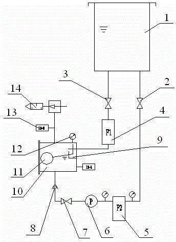
[0018] A cycle continuous degassing device, its structure is as follows figure 1 As shown, it includes a liquid storage tank 1 and a degassing tank 10 communicated through pipelines, and the pipeline between the liquid outlet of the liquid storage tank 1 and the liquid inlet of the degassing tank 10 is sequentially connected with a pump suction ball valve 3 and a coarse filter. 4, the pipeline between the liquid outlet of the degassing tank 10 and the liquid return port of the liquid storage tank 1 is sequentially connected with a check valve 8, a ball valve 7 before the pump, a circulation pump 6, a fine filter 5 and a liquid return ball valve 2.

[0019] The degassing tank 10 is provided with a vacuum generator 14 and a liquid level switch 13, and the degassing tank 10 is provided with a float valve 11, which is located between the high liquid level and the...


PUM


Abstract

The invention discloses a circular and continuous degassing device. The circular and continuous degassing device comprises a liquid storage tank and a degassing tank which are communicated through pipelines, wherein the pipeline between the liquid outlet of the liquid storage tank and the liquid inlet of the degassing tank is provided with a coarse filter; the pipeline between the liquid outlet of the degassing tank and the liquid return port of the liquid storage tank is provided with a circulating pump and a fine filter; the degassing tank is further provided with a vacuum generator and a liquid level switch; the degassing tank is also internally provided with a floating valve for controlling the liquid inlet of the degassing tank to open or close; a floating ball of the floating valve is positioned between the high liquid level and the low liquid level limited by the liquid level switch. The circular and continuous degassing device is simple in pipeline, stable for performance, low in cost, easy to maintain and low for requirement on degassed liquid, and can prevent repeated starting of the circulating pump on the basis of realizing stable and continuous degassing, thus prolonging the service life of the circulating pump.

Description

technical field [0001] The invention relates to the field of chemical machinery, in particular to a degassing device for degassing chemical raw material solutions. Background technique [0002] Chemical raw material solutions in industrial production often contain certain volatile gases, such as hydrogen sulfide, sulfur dioxide, etc. This gas not only has a certain negative effect on the quality of the product, but also pollutes the environment of the production workshop and further affects human health. ; Especially in the ultrasonic cleaning industry, if the gas content of the liquid is too high, it will inhibit the cavitation effect of the ultrasonic wave and further affect the cleaning effect. Therefore, the chemical raw material solution needs to be degassed before it is put into production. [0003] The degassing device is mainly divided into intermittent degassing device and continuous degassing device according to the working mode. Among them: the structure of the i...

Claims


Application Information

Patent Timeline
Patent Type & Authority Patents(China)
IPC IPC(8): B01D19/00
Inventor 韦自利
Owner 广东博思杜尔实业有限公司
Learn More