Rail switch lifting device

A technology of lifting device and switch, which is applied in metal processing equipment, metal rolling, manufacturing tools, etc., can solve the problems of running piles, complex structure, and easy damage.

Inactive Publication Date: 2014-01-01
XINXING DUCTILE IRON PIPES CO LTD
View PDF6 Cites 2 Cited by
  • Summary
  • Abstract
  • Description
  • Claims
  • Application Information

AI Technical Summary

Problems solved by technology

[0003] Current problems: the lifting of the front switch of the flying shear is composed of a swing cylinder, a gear, a rack and a guide arm. The str

Method used


Image

  • Rail switch lifting device
  • Rail switch lifting device

Examples


Embodiment Construction

[0018] The present invention will be further described in detail below in conjunction with the accompanying drawings and specific embodiments.

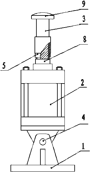
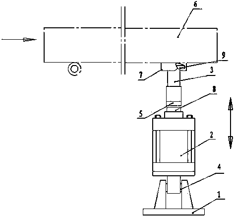
[0019] Such as figure 1 The point switch lifting device shown includes a support base 1, a cylinder 2 and a connecting block 3. The clip 9 at the upper end of the connecting block 3 is in clearance fit with the slot 7 under the steel rail 6, and the clip 9 is in the Can swing laterally in the draw-in groove 7, the chuck 9 on the upper end of the connecting block is preferably a spherical crown, which can reduce the friction between the connecting block 3 and the steel track 6; The connection is preferably a threaded connection, and a lock nut 5 is arranged between the connecting block 3 and the guide post 8 of the cylinder 2 to play a reinforcing role; 3. The top is spherical, and the cylinder 2 can preferably be a heavy-duty cylinder of the type QGBZ125*60-MP3 produced by Jinan Jiefeite Cylinder Co., Ltd.; the connection between the...


PUM


Abstract

The invention discloses a rail switch lifting device and relates to the technical field of rolling equipment. The rail switch lifting device comprises a support, a cylinder and a connector. A clamp at the upper end of the connector is in clearance fit with a clamp groove formed in the lower surface of a steel rail and can transversely swing in the same. The lower end of the connector is connected with a guide pillar of the cylinder, and the lower end of the cylinder is hinged to the support. Lifting of the guide pillar of the cylinder drives lifting of a rail switch. Some deflection of the rail switch relative to the support can be guaranteed since the lower end of the cylinder is hinged to the support and the clamp at the upper end of the connector is in clearance fit with the clamp groove in the lower surface of the steel rail. Threaded connection of the connector and the upper end of the cylinder facilitates mounting. Former structures of oscillating cylinders, gears, racks and guide arms are substituted by the rail switch lifting device, and lifting of the rail switch is simplified on the premise of meeting lifting requirements. The rail switch lifting device has the advantages of simple structure, convenience in operation and maintenance, low cost and practicality.

Description

technical field [0001] The invention relates to the technical field of steel rolling equipment. Background technique [0002] The production process of the high-speed wire is as follows: After the steel billet is heated by the heating furnace, it is rolled by 14 rough-and-middle rolling leveling and vertical rolling mills and 4 pre-finishing rolling mills, and then sent to the flying shear by the switch to remove the head (after multiple rolling Head cracking), enter 10 finishing mills to be rolled into finished products and 3-stage water-cooled boxes, then pass through pinch rollers and laying heads, enter the air-cooled roller table to cool down and cool down to the collection area for bundling and packaging. There is a hinge shaft at the end of the steel material track. Before the steel material enters the flying shear along the track, it is lifted to the top position by the switch connected to the slot under the track. The steel material behind the flying shear head ente...

Claims


Application Information

Patent Timeline
IPC IPC(8): B21B39/00
Inventor 张占涛
Owner XINXING DUCTILE IRON PIPES CO LTD
Why Eureka
Try Eureka