A floating bearing cylinder

A floating support and oil cylinder technology, applied in the field of support oil cylinders, can solve the problems of shortened service life, high ball receiving stress, short service life, etc., and achieve the effect of improving support force and large support force

Active Publication Date: 2015-10-21
毕晴春 +1
View PDF6 Cites 0 Cited by
  • Summary
  • Abstract
  • Description
  • Claims
  • Application Information

AI Technical Summary

Problems solved by technology

[0005] Secondly, in the existing hydraulic floating bearing oil cylinder, the opposite surface of the support piston and the collet (elastomer) is a matching smooth tapered surface, so that the steel ball is in point contact with the elastic body and the support piston respectively. Such a structure As a result, the ball receiving stress between the steel ball and the elastic body and the support piston is relatively large, which will reduce the bearing capacity of the support cylinder to a certain extent, and at the same time shorten the service life, and affect the mechanical properties of the material used for the collet (elastomer). High characteristic requirements, otherwise the service life will be shorter

Method used


Image

  • A floating bearing cylinder
  • A floating bearing cylinder
  • A floating bearing cylinder

Examples


no. 1 example

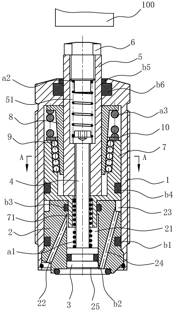
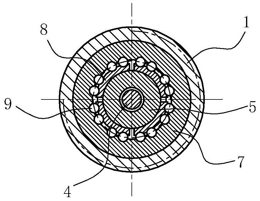
[0026] The first embodiment: as Figure 1 to Figure 6 As shown, the hydraulic floating support cylinder in this embodiment includes a cylinder body 1, an ejector device and a support clamping device, wherein the inner diameter of the cylinder body 1 is 24 mm, the outer wall has external threads, the upper end surface has a through hole, and the lower port is open. The ejector device includes a base 2, an ejector piston 3, an ejector rod 4, a return spring a1, a support rod 5 and an ejector spring a2, and the base 2 is positioned in the lower port of the cylinder body 1, and the base 2 and the cylinder 1 is provided with a first sealing ring b1, so that the base 2 is sealed and blocked in the lower port of the cylinder 1; the base 2 is also provided with a piston channel 21 in the axial direction. In this embodiment, the piston channel The diameter of the upper part of 21 is smaller than the diameter of the lower part, and the above-mentioned ejector piston 3 is located in the ...


PUM


Abstract

The invention relates to a floating supporting oil cylinder. The floating supporting oil cylinder comprises a cylinder body, an ejection device and a supporting clamping device, wherein the ejection device comprises a base, an ejection piston, an ejection rod, a back spring and a supporting rod; the base is provided with a piston channel; the ejection piston is positioned in the piston channel; the ejection rod is fixed with the ejection piston; the back spring is sleeved on the ejection rod; the supporting rod is pushed by the ejection rod; the supporting clamping device comprises a supporting piston and an elastic body; the supporting piston is positioned in the cylinder body; the elastic body is sleeved between the supporting rod and the supporting piston; the inner surface of the supporting piston and the outer surface of the elastic body are respectively an inner conical surface and an outer conical surface which are matched with each other; and steel balls are arranged between the inner conical surface and the outer conical surface. The floating supporting oil cylinder is characterized in that a hollow cylindrical boss is arranged at the lower end of the supporting piston and extends in the piston channel of the base; and the upper end of the ejection rod is matched with the supporting rod after penetrating in the cylindrical boss. The supporting force can be obviously increased under the condition that the cylinder diameter and the pressure are not changed, and the purpose of small size and large supporting force under the condition of low pressure is realized.

Description

technical field [0001] The invention relates to a supporting oil cylinder, in particular to a hydraulic floating supporting oil cylinder which can increase the supporting force of a workpiece by increasing the force-bearing area of ​​the piston. Background technique [0002] The hydraulic floating support cylinder is mainly used in mechanical processing. After being in contact with the workpiece to be processed, it generates a supporting force on the workpiece to reduce the vibration of the workpiece during processing and prevent the deformation of the workpiece. A device that provides floating auxiliary support for processing workpieces. For example, the Chinese Patent Authorization Announcement No. CN201513409U discloses a hydraulic support cylinder structure, which includes: a hydraulic support cylinder body, a rising piston (extrusion piston) installed in the body, and a plunger pushed by the rising piston (support rod), plunger spring (ejection spring), and a collet (e...

Claims


Application Information

Patent Timeline
Patent Type & Authority Patents(China)
IPC IPC(8): F15B15/14F15B15/20
Inventor 毕晴春
Owner 毕晴春
Why Eureka
Try Eureka