

Flash memory quality detection method and device
A quality detection method and flash memory technology, applied in static memory, instruments, etc., can solve the problems of long time consumption and low efficiency of flash memory detection technology, and achieve the effect of improving the utilization rate of flash memory
- Summary
- Abstract
- Description
- Claims
- Application Information
AI Technical Summary
Problems solved by technology
Method used
Image

Examples
Embodiment 1
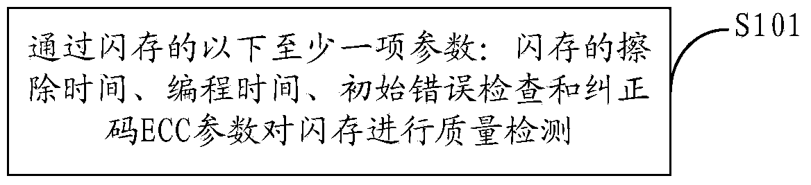
[0022] figure 1 The implementation flow of the flash memory quality detection method provided by Embodiment 1 of the present invention is shown, and the process of the method is described in detail as follows:
[0023] In step S101, the quality of the flash memory is inspected through at least one of the following parameters of the flash memory: erasing time, programming time, initial error check and ECC parameters of the flash memory.
[0024] Exemplarily, the quality detection of the flash memory through the erasing time of the flash memory includes:
[0025] Extracting N sample blocks from the same layer of the flash memory chip, where N is an integer greater than or equal to 1;
[0026] Perform an erasing (charging) operation on each of the N sample blocks, that is, charge the storage cells inside the flash memory chip; specifically, sequentially charge each of the N sample blocks Erase (charge) operation for each sample block;
[0027] After the erasing operation, perf...
Embodiment 2
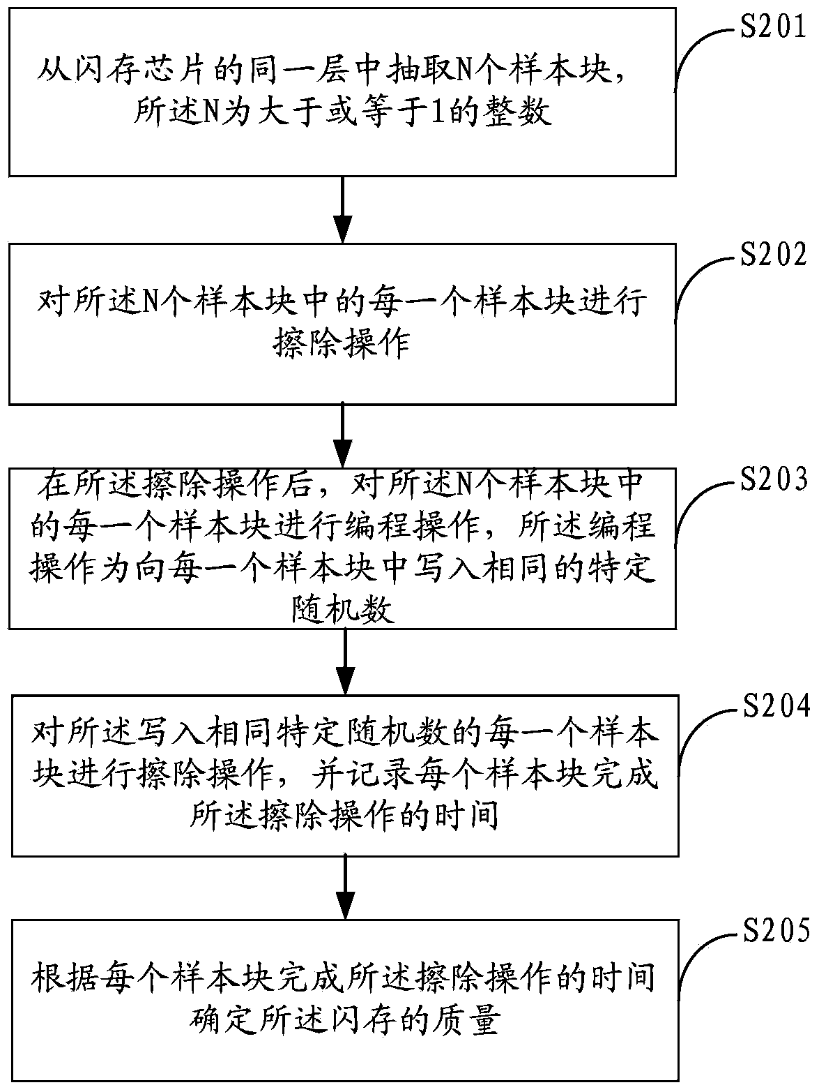
[0052] figure 2 The implementation flow of the flash memory quality detection method provided by the second embodiment of the present invention is shown, and the process of the method is described in detail as follows:
[0053] In step S201, N sample blocks are extracted from the same layer of the flash memory chip, where N is an integer greater than or equal to 1;
[0054] In step S202, an erasing operation is performed on each of the N sample blocks;
[0055] In step S203, after the erasing operation, perform a programming operation on each of the N sample blocks, the programming operation is to write the same specific random number into each sample block;
[0056] In step S204, perform an erasing operation on each sample block written with the same specific random number, and record the time when each sample block completes the erasing operation;
[0057] In step S205, the quality of the flash memory is determined according to the time when each sample block completes th...
Embodiment 3
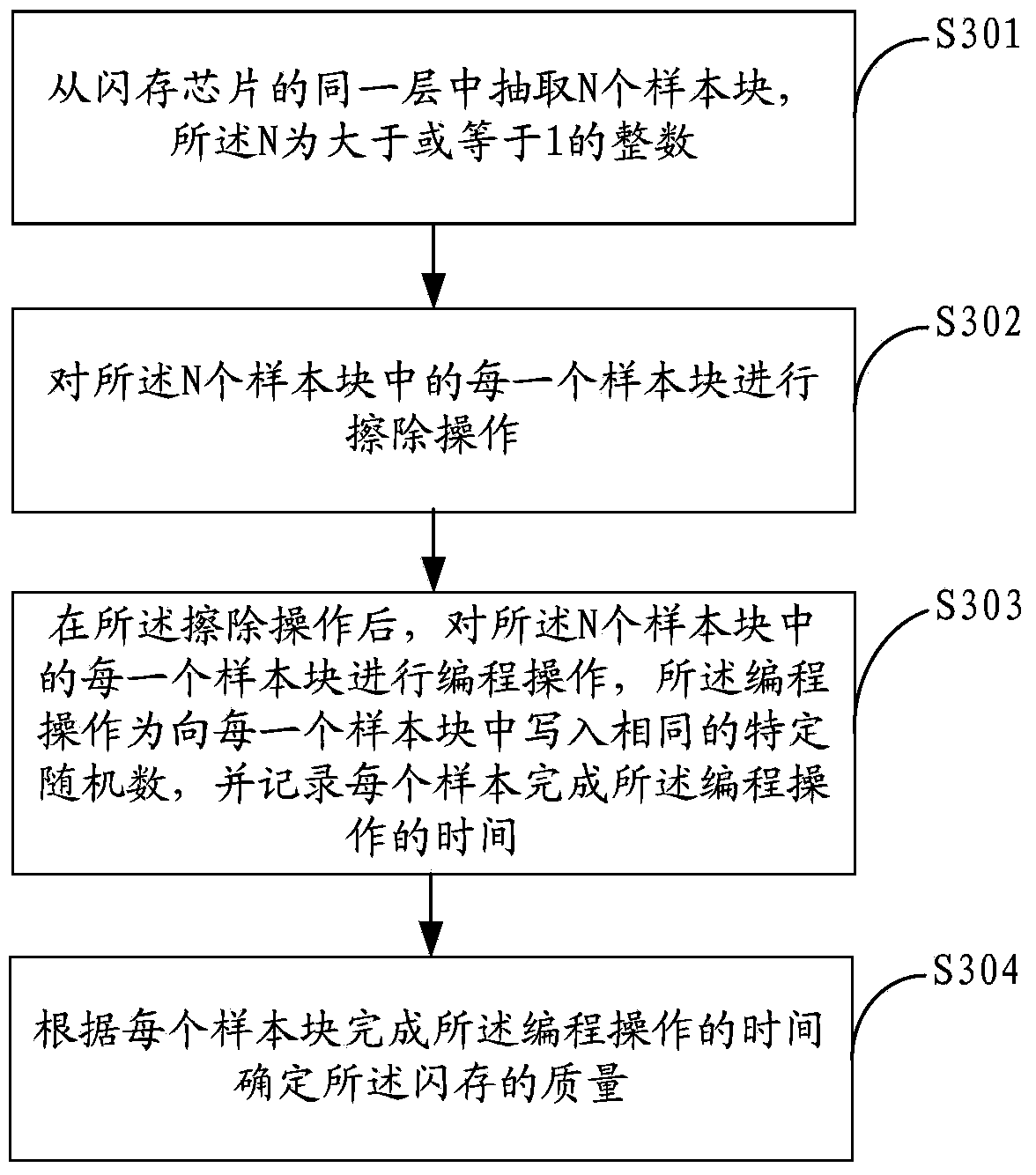
[0060] image 3 The implementation flow of the flash memory quality detection method provided by Embodiment 3 of the present invention is shown, and the process of the method is described in detail as follows:
[0061] In step S301, N sample blocks are extracted from the same layer of the flash memory chip, where N is an integer greater than or equal to 1;
[0062] In step S302, an erasing operation is performed on each of the N sample blocks;
[0063] In step S303, after the erasing operation, perform a programming operation on each of the N sample blocks, the programming operation is to write the same specific random number into each sample block, and recording the time for each sample block to complete the programming operation;
[0064] In step S304, the quality of the flash memory is determined according to the time for each sample block to complete the programming operation. Specifically, according to the time for each sample block to complete the programming operatio...
PUM
 Abstract
Description
Claims
Application Information