
Residual-current circuit breaker

A leakage circuit breaker and circuit breaker technology, applied in the direction of protection switch operation/release mechanism, etc., can solve the problems of small contact pressure, burnout of internal components of the circuit breaker, and temperature rise of the circuit breaker, so as to reduce the loss of force and simplify the structure , the effect of short action time

Inactive Publication Date: 2014-01-01
浙江胜宇电气科技有限公司
View PDF5 Cites 13 Cited by
  • Summary
  • Abstract
  • Description
  • Claims
  • Application Information

AI Technical Summary

Problems solved by technology

[0002] The leakage circuit breaker is actually a circuit breaker with leakage protection function. The leakage circuit breaker includes a circuit breaker tripping mechanism and a leakage detection system, but the existing leakage detection system is to trip the circuit breaker through a connecting rod. The moving contact of the circuit breaker in the mechanism remains connected, that is, after the leakage detection system detects the leakage of the circuit, it drives the moving contact of the circuit breaker through the connecting rod, and then realizes the breaking and tripping through the tripping mechanism of the circuit breaker, so that the indirect breaking and tripping The buckle method makes the contact pressure of the dynamic and static contacts of the circuit breaker too small, and it is easy to cause a high internal temperature rise of the circuit breaker when the circuit breaker is tripped, which easily causes the internal components of the circuit breaker to be burned when the circuit breaker is broken.

Method used


Image

  • Residual-current circuit breaker
  • Residual-current circuit breaker
  • Residual-current circuit breaker

Examples


Embodiment Construction

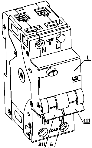
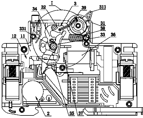
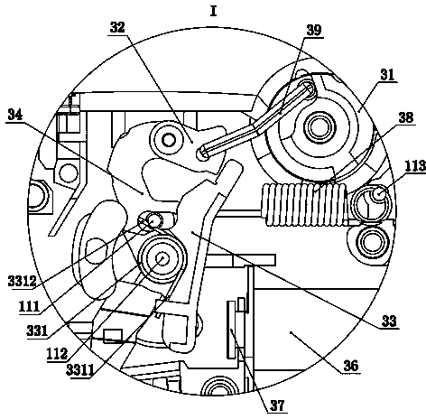
[0016] Such as figure 1 , 2 , 3, 4, 5, 6, and 7 show a leakage circuit breaker, including an outer casing 1, and an intermediate partition 11 is provided in the inner cavity of the outer casing 1, and the intermediate partition 11 will The inner cavity of the outer casing 1 is divided into left and right concave cavities 12 and right concave cavities 13 which are left and right symmetrical, wherein the left concave cavity 12 is equipped with a leakage detection system 2 and a leakage protection device connected to the leakage detection system 2 Tripping mechanism 3, described leakage protection tripping mechanism 3 includes leakage protection handle 31, leakage protection jumper 32, leakage protection lock 33, leakage protection moving contact 34, leakage protection static contact 35, leakage protection electromagnetic Coil 36, leakage protection push rod 37, leakage protection contact tension spring 38, the leakage protection handle 31 is hingedly mounted on the outer shell ...


PUM


Abstract

The invention discloses a residual-current circuit breaker. The residual-current circuit breaker comprises an outer shell body, wherein a middle partition plate is arranged in an inner cavity of the outer shell body, the inner cavity of the outer shell body is divided into a left concave cavity and a right concave cavity through the middle partition plate, the left concave cavity is symmetrical to the right concave cavity in a bilateral mode, an electric leakage detection system is arranged in the left concave cavity, and a breaker tripping mechanism is arranged in the right concave cavity. The residual-current circuit breaker is characterized in that an electric leakage protection tripping mechanism which is connected with the electric leakage detection system is further arranged in the left concave cavity, and the electric leakage protection tripping mechanism comprises an electric leakage protection handle, an electric leakage protection jump buckle, an electric leakage protection lock catch, an electric leakage protection moving contact, an electric leakage protection fixed contact, an electric leakage protection electromagnetic coil and an electric leakage protection ejector rod. Due to the adoption of the structure, the residual-current circuit breaker is more reasonable in structure, safer to use and capable of greatly improving a rated current.

Description

technical field [0001] The invention relates to a leakage circuit breaker. Background technique [0002] The leakage circuit breaker is actually a circuit breaker with leakage protection function. The leakage circuit breaker includes a circuit breaker tripping mechanism and a leakage detection system, but the existing leakage detection system is to trip the circuit breaker through a connecting rod. The moving contact of the circuit breaker in the mechanism remains connected, that is, after the leakage detection system detects the leakage of the circuit, it drives the moving contact of the circuit breaker through the connecting rod, and then realizes the breaking and tripping through the tripping mechanism of the circuit breaker, so that the indirect breaking and tripping The buckle method makes the contact pressure of the dynamic and static contacts of the circuit breaker too small, which will easily cause a high internal temperature rise of the circuit breaker when the circ...

Claims


Application Information

Patent Timeline
IPC IPC(8): H01H71/24
Inventor 张峰黄胜宇
Owner 浙江胜宇电气科技有限公司
Learn More