High-gain 3-Z type Boost circuit

A 3-Z, high-gain technology, applied in the direction of conversion equipment without intermediate conversion to AC, can solve the problems of increased switching tubes, high cost, decreased stability and reliability, etc.

Active Publication Date: 2014-01-01
SOUTH CHINA UNIV OF TECH
View PDF3 Cites 11 Cited by
  • Summary
  • Abstract
  • Description
  • Claims
  • Application Information

AI Technical Summary

Problems solved by technology

The traditional Boost circuit can no longer meet the needs of the industry, and the industry needs a higher gain boost circuit
The traditional method is to boost the voltage by cascading multiple Boost link circuits. This method is costly, and due to the increase in the number of switch tubes, the stability and reliability of the system will decline. If one of the links crashes, the entire system will be damaged. collapse

Method used


Image

  • High-gain 3-Z type Boost circuit
  • High-gain 3-Z type Boost circuit
  • High-gain 3-Z type Boost circuit

Examples


Embodiment Construction

[0012] The specific implementation of the present invention will be further described below in conjunction with the accompanying drawings, but the implementation and protection scope of the present invention are not limited thereto.

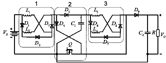
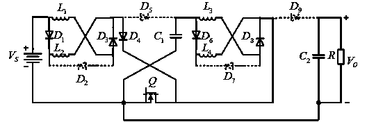
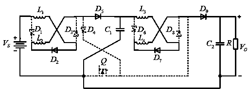
[0013] refer to figure 1 , the high-gain 3-Z boost circuit of the present invention mainly includes a first Z network 1, a second Z network 2, a third Z network 3 and an output circuit. In the high-gain Z network structure Boost circuit of the present invention, the first Z network 1 is used as a first-stage boost module; the third Z network 3 is used as a second-stage boost module; the second Z network 2 is used as a switch switch module; ninth diode D 9 , the second energy storage capacitor C 2 and load R for the output module. When the switch tube Q is turned on, the power supply simultaneously supplies the first inductor L in the first Z network 1 1 and the second inductance L 2 For parallel charging, the first energy storage capacitor C...


PUM


Abstract

The invention provides a high-gain 3-Z type Boost circuit which comprises a first Z network, a second Z network, a third Z network and an output circuit. The first Z network is used as a first-stage boosting module, the third Z network is used as a second-stage boosting module, the second Z network is used as an on-off switching module, and a ninth diode, a second energy storage capacitor and a load are used as an output module. When a switch pipe is connected, a power source is connected in parallel with two inductors and charges the two inductors in the first Z network, a first energy storage capacitor is connected in parallel with two inductors and charges the two inductors in the second Z network, and the second energy storage capacitor discharges the load. When the switch pipe is disconnected, the power source is connected in series with the fist inductor, and then is connected in series with the second inductor to charge the first energy storage capacitor, and therefore the first-stage boosting is finished; the first-stage boosting module is connected in series with the third inductor and then is connected in series with the fourth inductor to charge the second energy storage capacitor, and therefore the second-stage boosting is finished. Only one switch pipe is used in the whole circuit, and high output voltage gain can be achieved.

Description

technical field [0001] The invention relates to the technical field of power electronic circuits, in particular to a high-gain 3-Z type Boost circuit. Background technique [0002] With the development of life and industry, the requirements for power electronic circuits are becoming increasingly stringent. The traditional boost circuit can no longer meet the needs of the industry, and the industry needs a higher gain boost circuit. The traditional method is to boost the voltage by cascading multiple Boost link circuits. This method is costly, and due to the increase in the number of switch tubes, the stability and reliability of the system will decline. If one of the links crashes, the entire system will be damaged. collapse. Contents of the invention [0003] The object of the present invention is to overcome the shortcomings of the above-mentioned prior art and provide a high-gain 3-Z type Boost circuit. The invention is suitable for power electronic circuits requirin...

Claims


Application Information

Patent Timeline
Patent Type & Authority Applications(China)
IPC IPC(8): H02M3/07
Inventor 张波张桂东杨立强丘东元肖文勋黄子田
Owner SOUTH CHINA UNIV OF TECH
Why Eureka
Try Eureka