
Cutting apparatus

A technology of cutting equipment and equipment, applied in thin material processing, metal processing, transportation and packaging, etc., to achieve the effect of cheap structure, simple structure and high productivity

Active Publication Date: 2014-01-01
MANZ ITAL
View PDF6 Cites 6 Cited by
  • Summary
  • Abstract
  • Description
  • Claims
  • Application Information

AI Technical Summary

Problems solved by technology

A problem in the prior art is to achieve an effective balance between quality and productivity when performing the operation of cutting battery cells

Method used


Image

  • Cutting apparatus
  • Cutting apparatus
  • Cutting apparatus

Examples


Embodiment Construction

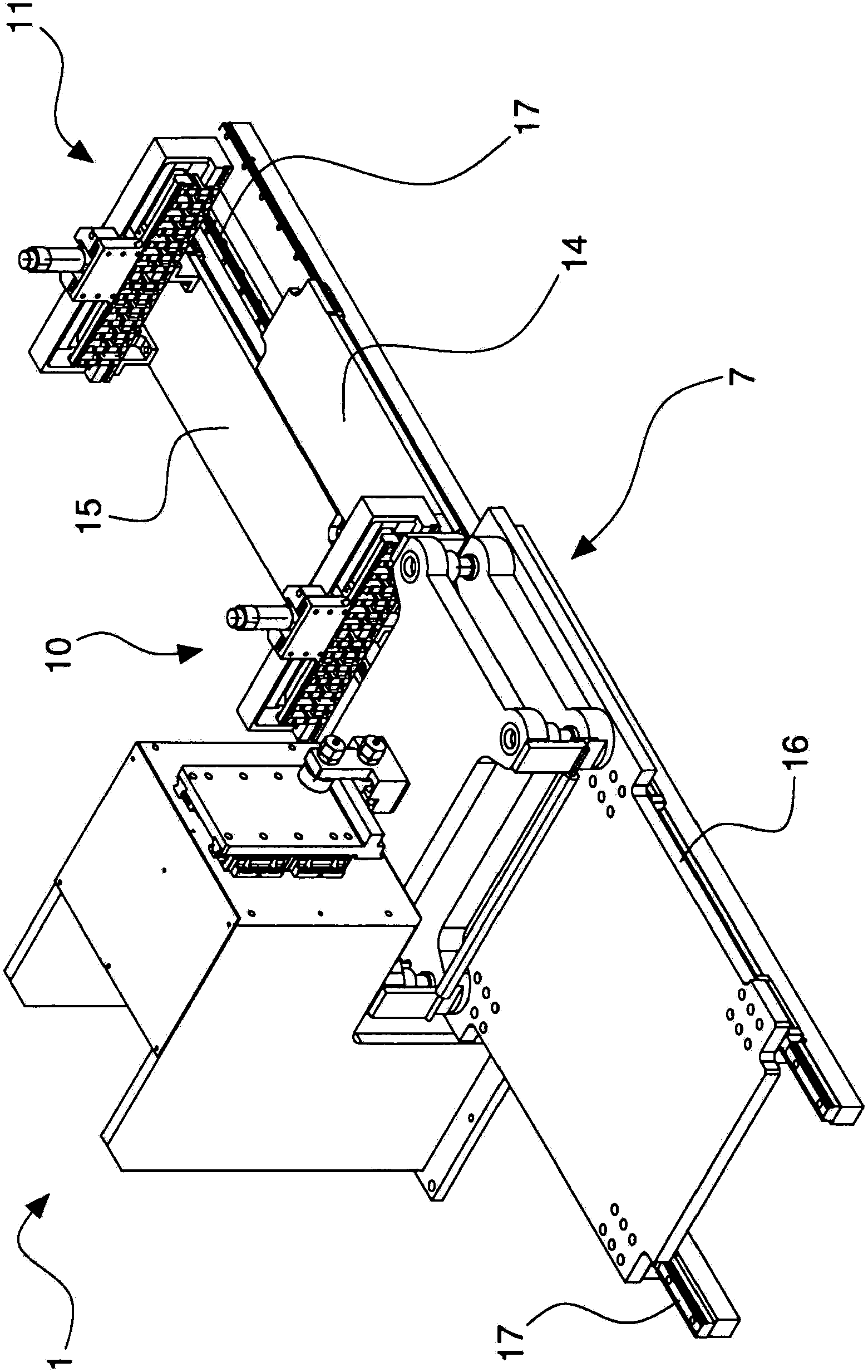
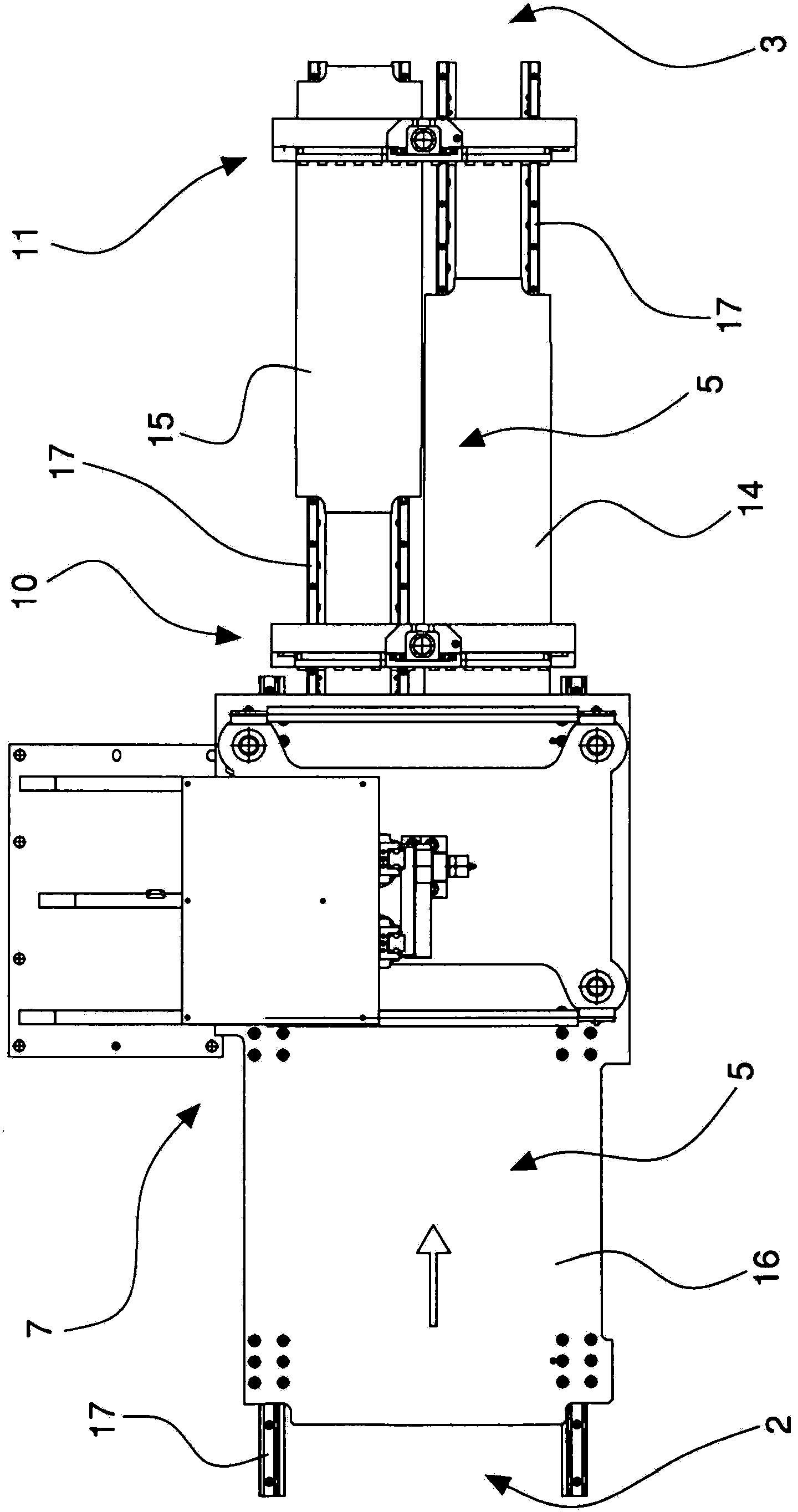
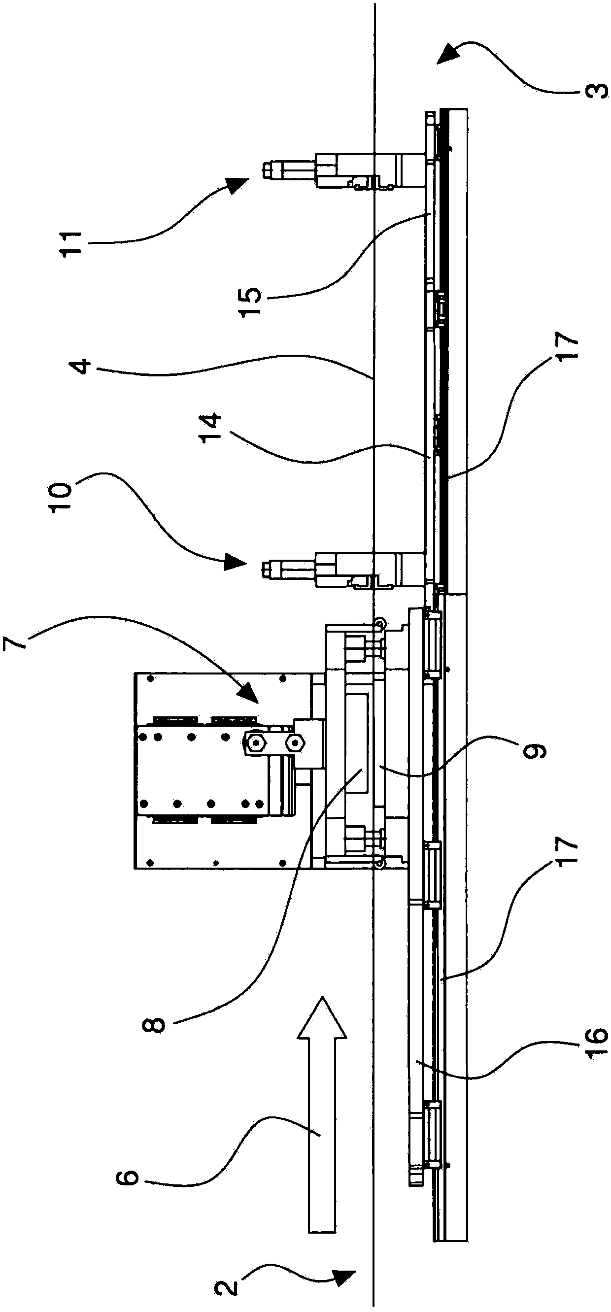
[0022] With reference to the above-mentioned figures, a cutting device has been denoted in its entirety by the reference number 1 , in particular a cutting device for cutting a continuous flat element, for example in the form of a strip, which advances in a continuous advancing motion. In a specific example, the cutting device 1 is configured for cutting a part of the contour of electrochemical cells, for example for lithium batteries, arranged in rows for forming a continuous element. In particular, the cutting device may be used to cut the terminals of electrochemical cells which will form the electrical contacts of the assembled battery.

[0023] As in a particular example, the cutting device 1 can be operated for cutting predetermined regions of a continuous element in such a way that its continuity is preserved (e.g. of electrochemical cells arranged in rows on the continuous element). terminals).

[0024] The cutting device 1 may be part of a machine for manufacturing e...


PUM


Abstract

In a cutting apparatus, a continuous element with a row of electrochemical cells for lithium batteries is supplied along a supplying path on which there are arranged, one after another, a cutting device (7) and two dragging devices (10; 11), each having a shuttle element (14; 15) that has an operating unit (12; 13) operationally associated with the continuous element.

Description

Background technique [0001] The invention relates to a cutting device, in particular for cutting flat elements. [0002] In particular, it relates to a cutting device which can be adapted to cut a continuous flat element, for example in the form of a continuous strip or film unwound from a reel, in a predetermined position. [0003] In particular, but not exclusively, the invention may be used to cut partial contours (electrodes) of flat elements that can be used to fabricate electrochemical cell packs for forming batteries (eg, lithium batteries). [0004] A cutting device is known in which a continuous element comprising a row of electrochemical cells with flat electrodes is fed by an intermittent motion to a cutting device having a punch and a die, so The punches and dies described are intermittently opened and closed with a cutting motion coordinated with the intermittent advancing motion of the continuous element to form terminals that act as electrical contacts for the ...

Claims


Application Information

Patent Timeline
Patent Type & Authority Applications(China)
IPC IPC(8): B26D1/60B26D7/06
CPCB26D5/02B26F1/40B65H2403/55B26D5/20B65H20/16B26D1/60B65H2405/52B26D7/015B26D1/605B65H2220/09Y10T83/4763Y10T83/0515Y10T83/4757
Inventor M·塞尔E·博托里尼
Owner MANZ ITAL
Learn More