Wind power plant

A ring-shaped, pontoon technology, applied in wind power generation, wind engines, wind engines at right angles to the wind direction, etc., can solve the problem that wind power stations cannot be installed in deep-water shelf areas

Active Publication Date: 2014-01-01
FEDERAL STATE BUDGETARY INSTITUTIONFEDERAL AGENCY FOR LEGAL PROTECTION OF MILITARY SPECIAL & DUAL USE INTELLECTUAL ACTIVITY RESULTSFSBIFALPIAR +1
View PDF4 Cites 5 Cited by
  • Summary
  • Abstract
  • Description
  • Claims
  • Application Information

AI Technical Summary

Problems solved by technology

[0007] The disadvantage of this prototype is that the wind power plant cannot be in...

Method used


Image

  • Wind power plant
  • Wind power plant
  • Wind power plant

Examples


Embodiment Construction

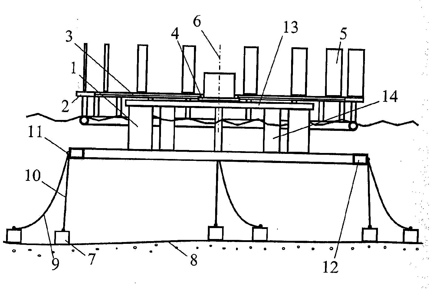
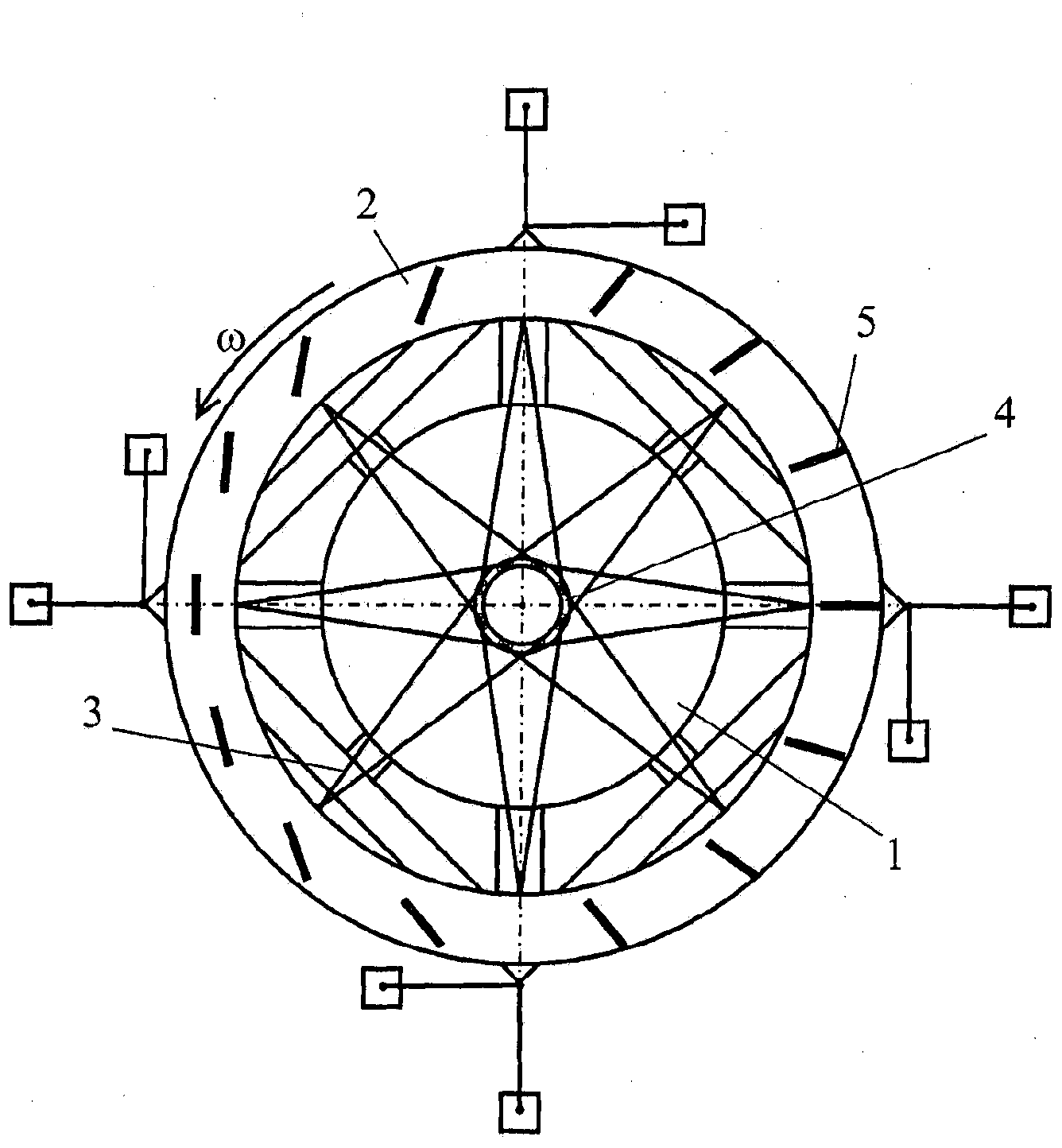
[0024] The wind power plant comprises a platform 1 surrounded by an annular pontoon 2, a kinematic mechanism 3 capable of transferring the rotational energy of the annular pontoon 2 to a receiving unit 4 of an energy converter (the energy converter is not fully shown in the figure).

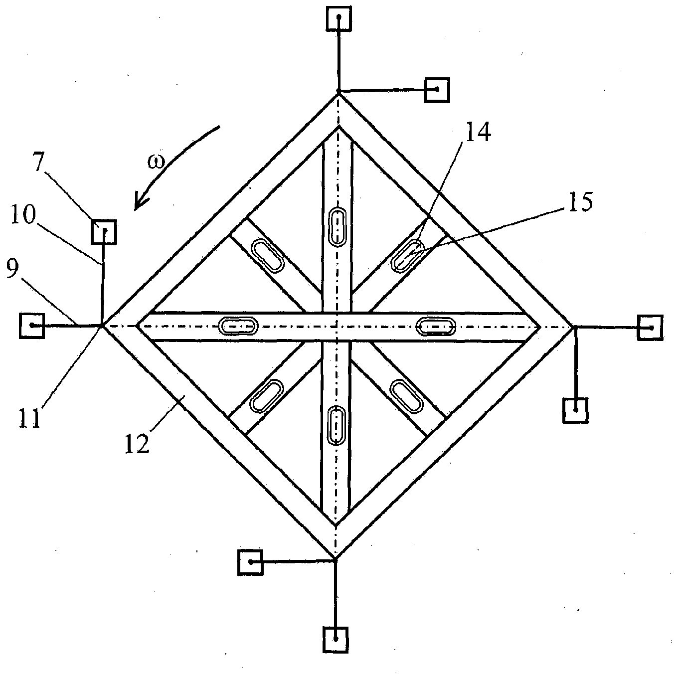
[0025] The blades 5 are arranged on an annular pontoon 2 rotatable relative to a vertical axis 6 . The platform 1 is formed to be floatable and is provided with positioning means comprising at least 6 anchors 7 located on the bottom 8 of the body of water, preferably in pairs, and by means of flexible members (cables or chains) 9 and 10 are connected to the platform 1 such that the horizontal plane projection of one flexible member 9 is oriented radially to the axis of rotation 6 of the annular pontoon 2 and the projection of the second flexible member 10 is oriented tangentially, the anchor 7 connected to it relative to the flexible The points 11 of attachment of the members 9 and 10 to the floa...


PUM


Abstract

The wind power plant includes blades mounted on an annular pontoon. The pontoon is rotatable about a vertical axis. An energy converter is situated on a platform that is encircled by the annular pontoon. A kinematic mechanism is designed so as to be capable of transmitting the rotational energy of the annular pontoon to the receiving unit of the energy converter. The floating platform is equipped with positioning means that include at least six anchors located on the bottom of a body of water. The anchors are connected to the platform by flexible members and are offset in a direction opposite to the direction of rotation of the annular pontoon relative to the point at which the flexible member is attached to the platform. The technical result is an increase in the number of places where the wind power plants can be installed and an increase in electric power generation.

Description

technical field [0001] The invention relates to small scale power generation and can be used to generate wind farms. Background technique [0002] There is known a wind power plant comprising wind-receiving working elements arranged on an annular pontoon and an energy converter kinematically connected to the pontoon (Soviet Inventor's Certificate No. 1719713, IPC5F03D 3 / 06; 1992). [0003] The disadvantage of this solution is that the transfer of mechanical energy to the generator is complicated, especially when the wheel size increases, due to the forces that move the pontoon radially during its rotation. Thus, the pontoon efficiently interacts only with those generators to which the force acts. Furthermore, it is necessary to construct an annular channel (or at least install several support members (stops) along the periphery of the pontoon), which significantly complicates and increases the price of the power station installation. [0004] Also known are wind power plan...

Claims


Application Information

Patent Timeline
IPC IPC(8): F03D3/06
CPCF03D3/005B63B35/44F05B2240/93B63B21/50Y02E10/74B63B2035/446B63B2241/08F03D3/067F03D13/25Y02E10/727
Inventor 维克托·瓦烈里耶维奇·切博克萨罗夫
Owner FEDERAL STATE BUDGETARY INSTITUTIONFEDERAL AGENCY FOR LEGAL PROTECTION OF MILITARY SPECIAL & DUAL USE INTELLECTUAL ACTIVITY RESULTSFSBIFALPIAR
Why Eureka
Try Eureka