Filter sealing plate continuous punch forming die and feed mechanism

A technology of stamping forming and feeding mechanism, which is applied to forming tools, manufacturing tools, metal processing equipment, etc., can solve the problems of high equipment manufacturing cost, low work efficiency and high labor intensity of workers

Inactive Publication Date: 2014-01-08
李勇
View PDF8 Cites 9 Cited by
  • Summary
  • Abstract
  • Description
  • Claims
  • Application Information

AI Technical Summary

Problems solved by technology

[0002] When the filter used in vehicles (such as the rotary filter element) manufactures its sealing plate, the existing technology usually punches the steel plate into individual circular sheets one by one by a punching machine, and then puts the circular sheet on the Stretch in the stretching mold, take it out after stretching, and put it in the first molding mold for the first compression molding, then take it out and put it in the second molding mold for the second compression molding, and then Take it out and put

Method used


Image

  • Filter sealing plate continuous punch forming die and feed mechanism
  • Filter sealing plate continuous punch forming die and feed mechanism
  • Filter sealing plate continuous punch forming die and feed mechanism

Examples


Embodiment Construction

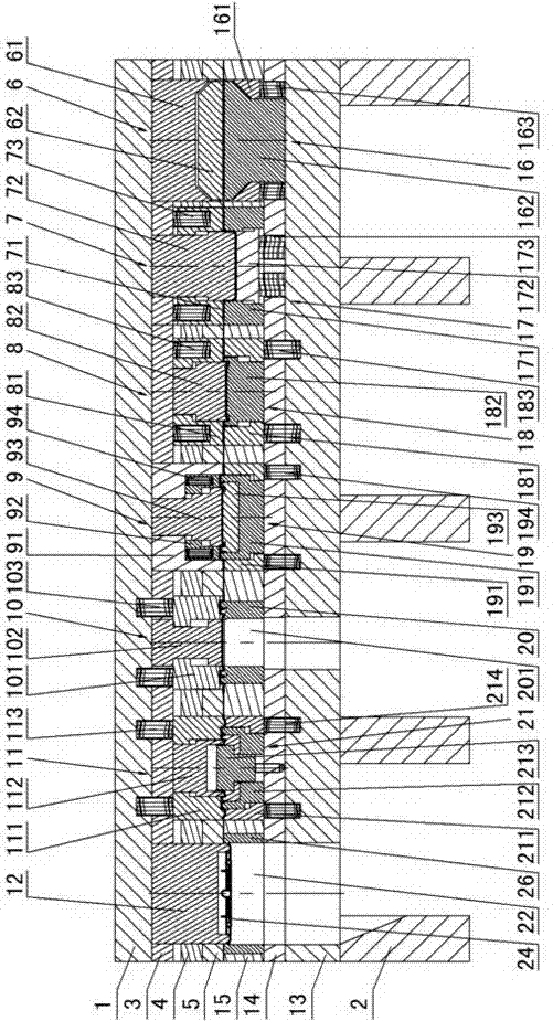
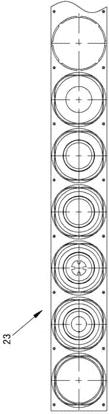
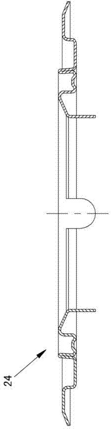
[0014] The invention relates to a continuous stamping mold and a feeding mechanism for a filter sealing plate, such as figure 1 — Figure 7As shown, it is characterized in that it includes an upper formwork 1 and mold feet 2, a fixed plate 3 is installed under the upper formwork, a stripping ring backing plate 4 is installed under the fixing plate, a stripping ring plate 5 is installed under the stripping ring backing plate, and The fixed plate under the upper template 1, the stripping ring backing plate and the stripping ring plate are successively equipped with a cutting ring upper die 6, a stretching upper die 7, a first molding upper die 8, and a second molding upper die 9 , punching upper die 10, turning hole upper die 11 and stripping module 12, described cutting ring upper die 6 includes cutting ring upper die base 61 and cutting ring upper die core 62, and described stretching upper die 7 includes stretching Upper die base 71 and stretching upper die core 72, stretchi...


PUM


Abstract

A filter sealing plate continuous punch forming die and a feed mechanism are characterized in that the filter sealing plate continuous punch forming die comprises an upper die plate and die feet, a fixing plate is arranged at the lower portion of the upper die plate, a stripping ring base plate is arranged at the lower portion of the fixing plate, a stripping ring plate is arranged at the lower portion of the stripping ring base plate, a circular ring cutting upper die, a stretching upper die, a primary die pressing upper die, a secondary die pressing upper die, a punching upper die, a hole flanging upper die and a die stripping block are sequentially arranged among the fixing plate, the stripping ring base plate and the stripping ring plate and below the upper die plate, a lower die plate is arranged on the die feet, a female die base plate is arranged on the lower die plate, a female die plate is arranged on the female die base plate, coil stock is arranged between the female die plate and the stripping ring plate, a circular ring cutting lower die, a stretching lower die, a primary die pressing lower die, a secondary die pressing lower die, a punching lower die and a hole flanging lower die are sequentially arranged between the female die base plate of the lower die plate and the female die plate of the lower die plate, stripping holes are formed in the position, corresponding to the die stripping block, of the female die plate, the position, corresponding to the die stripping block, of the female die base plate and the position, corresponding to the die stripping block, of the lower die plate respectively, and a workpiece formed through die pressing is stripped through the stripping holes.

Description

technical field [0001] The invention relates to processing equipment for automatic punching of a filter sealing plate, in particular to a continuous stamping forming mold and a feeding mechanism for a filter sealing plate. Background technique [0002] When the filter used in vehicles (such as the rotary filter element) manufactures its sealing plate, the existing technology usually punches the steel plate into individual circular sheets one by one by a punching machine, and then puts the circular sheet on the Stretch in the stretching mold, take it out after stretching, and put it in the first molding mold for the first compression molding, then take it out and put it in the second molding mold for the second compression molding, and then Take it out and put it in the punching mold for punching, and finally put it in the hole turning mold for hole turning and shaping. It is divided into 6 steps, and these 6 steps are all carried out separately, which cannot be operated cohe...

Claims


Application Information

Patent Timeline
IPC IPC(8): B21D37/10B21D43/04B21D43/26
Inventor 李华平
Owner 李勇
Why Eureka
Try Eureka