
A grooved brick production line

A production line and groove technology, applied in ceramic molding machines, ceramic molding workshops, manufacturing tools, etc., can solve the problems of difficult processing, waste of resources, pollution, etc., and achieve the advantages of saving raw material costs, smooth cutting section, and reducing environmental pollution. Effect

Active Publication Date: 2015-09-30
CHENGDU NO 4 CONSTR ENG +1
View PDF5 Cites 0 Cited by
  • Summary
  • Abstract
  • Description
  • Claims
  • Application Information

AI Technical Summary

Problems solved by technology

[0004] 1. At the unloading station, the operating efficiency of workers is unstable, and some bricks are often missed and not detected in time. The existing method is to directly discharge and stack the wet bricks. The disadvantage of this is that the wet bricks are easily deformed due to force , the unpicked adobes become waste, resulting in waste of resources
[0005] 2. Due to the need to ensure a flat section during cutting, the transmission device at the front end of the cutting tool is usually not suitable for high-speed transmission. Due to the lack of monitoring means, the existing brick cutting machine usually drives at the same speed at the front and rear sections, and the output efficiency and product quality are not good. It is difficult to meet the high-speed discharge requirements of the discharge conveyor belt in the rear stage
[0006] 3. The finished brick has a single shape, and it is difficult to knock the thin-walled edge on the surface of the brick and make it into a brick with grooves for piercing the pipeline. It can only be cut at the construction site, which is difficult to process, low in efficiency, and serious in pollution

Method used


Image

  • A grooved brick production line
  • A grooved brick production line
  • A grooved brick production line

Examples


Embodiment Construction

[0029] The present invention will be further described in detail below in conjunction with test examples and specific embodiments. However, it should not be understood that the scope of the above subject matter of the present invention is limited to the following embodiments, and all technologies realized based on the content of the present invention belong to the scope of the present invention.

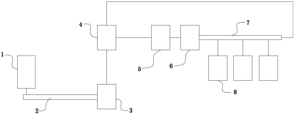
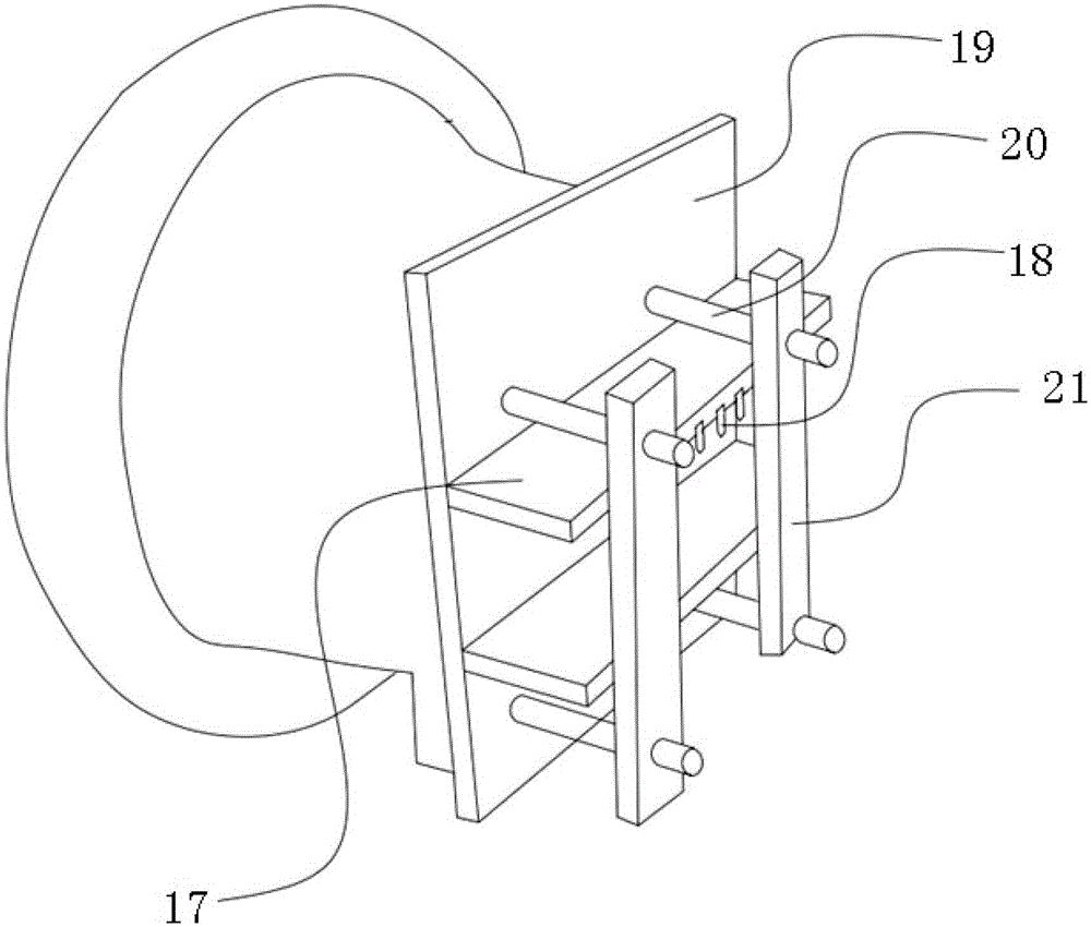
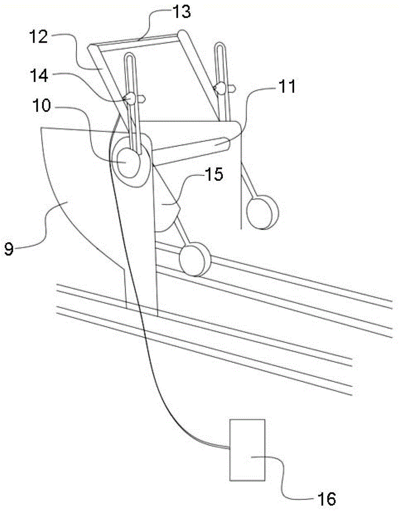
[0030] Such as Figure 1 to Figure 3 As shown, a trough-shaped brick production line in this embodiment includes a sand dredging device 1 and a raw material conveyor belt 2 arranged in a sand field. The discharge end of the raw material conveyor belt 2 is connected with the feeding end of the humidifying and mixing device 3. The discharge end of 3 is connected with the feed end of mud cylinder 4, and the discharge end of mud cylinder 4 is connected with the feed end of brick extruder 5, and the discharge end of brick extruder 5 is provided with brick cutter 6, and the brick cutter...


PUM


Abstract

The invention discloses a groove-shaped brick production line which comprises a sand dredging device arranged at a sand field and a raw material conveying belt. The discharge end of the raw material conveying belt is connected with the feeding end of a humidifying stirring device, the discharge end of the humidifying stirring device is connected with the feeding end of a mud cylinder, the discharge end of the mud cylinder is connected with the feeding end of a brick extruding machine, a brick cutting machine is arranged at the discharge end of the brick extruding machine, a blank conveying belt is arranged at the discharge end of the brick cutting machine, a plurality of unloading working stations are arranged at the side portion of the blank conveying belt, and a plurality of blank conveying trolleys are arranged on the unloading working stations; the tail end of the blank conveying belt is connected with the feeding end of the mud cylinder; due to the fact that the tail end of the blank conveying belt is connected with the mud cylinder, when the blank on the blank conveying belt is conveyed to the unloading working stations and is not completely unloaded, the blank is conveyed back in the mud cylinder to be used as raw materials for secondary utilization, raw material cost is saved, waste is reduced, and environmental pollution is reduced.

Description

technical field [0001] The invention relates to the field of a sintered brick production device, in particular to a grooved brick production line. Background technique [0002] At present, the main function of the strip cutting machine used in brick and tile production enterprises is to use the strip cutter to cut the mud strips extruded by the brick extrusion machine into shaped mud strips of equal length according to the different requirements of the final product, and then The adobe machine cuts again into the final qualified adobe. The working principle of ordinary strip cutting machine is that after the mud strip is extruded by high pressure from the outlet of the brick extruder, it first touches the passive roller of the strip cutter. Since the brick extruder works continuously, the mud strip is always used as the active part. After passing through the radius of rotation of the cutting wire, the cutting wire is a cylindrical cutting device composed of steel wires, whi...

Claims


Application Information

Patent Timeline
Patent Type & Authority Patents(China)
IPC IPC(8): B28B15/00B28B3/20
CPCB28B3/20B28B11/14B28B15/00
Inventor 刘和平廖晓东谢惠庆张雪如康清泉邓双合李苏铭吴学界张溯许刚陈蜀川李熊飞贾鹏坤宗伟
Owner CHENGDU NO 4 CONSTR ENG
Learn More