Low-wear brush type seal

A brush-type sealing, low-wear technology, applied in the direction of preventing leakage, engine components, machines/engines, etc., can solve the problems of rotor friction and wear friction heat, increasing the gap between the brush wire bundle and the rotor, and reducing the reliability of the brush wire, etc. Achieve the effect of improving reliability, improving stability and safety, improving friction and wear and heating

Inactive Publication Date: 2014-01-08
TSINGHUA UNIV
View PDF4 Cites 1 Cited by
  • Summary
  • Abstract
  • Description
  • Claims
  • Application Information

AI Technical Summary

Problems solved by technology

[0003] However, the brush seal is a contact seal, and the friction and wear between the brush filament bundle and the rotor will not only increase the gap between the brush filament bundle and the rotor, but may also cause obvious friction and wear to the rotor and cause Obvious frictional heat affects the stability and safety of rotor operation and reduces the reliability of brush filaments

Method used


Image

  • Low-wear brush type seal
  • Low-wear brush type seal
  • Low-wear brush type seal

Examples


Embodiment 1

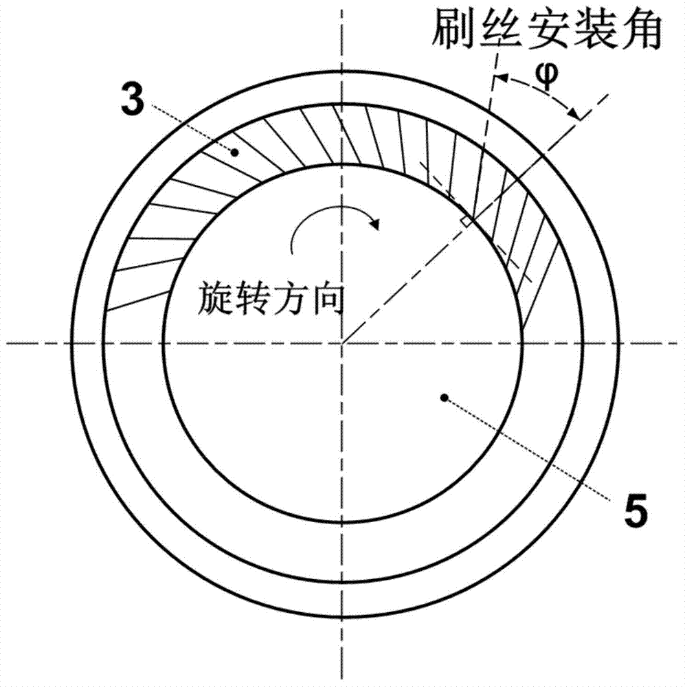
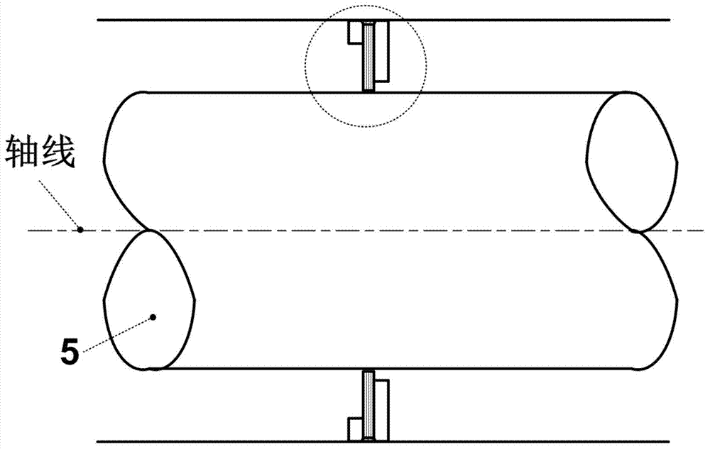
[0024] 3 is a schematic diagram of Embodiment 1 of the present invention. The brush seal structure includes a front baffle 1, a rear baffle 2, and a brush filament bundle 3. The root 4 of the brush filament bundle 3 is enclosed by the front baffle 1 and the rear baffle 2. The clamped brush filament bundle 3 is "blown down" under the upstream pressure to contact the rotor 5 to achieve a sealing effect and prevent the sealed fluid medium from leaking from upstream to downstream. Wherein, the brush filaments in the brush filament area 3 are not flush in the radial direction of the rotor 5, and the lengths of several downstream brush filaments of the brush filament bundle 3 are shorter than the upstream brush filaments, that is, from the axial direction of the rotor 5 to - Viewed on the radial plane, there is a gap 31 at the downstream free end of the brush filament bundle 3; the gap 31 is triangular when viewed on the axial-radial plane of the rotor 5 (refer to FIG. 3 ), and the a...

Embodiment 2

[0026] Figure 4 is a schematic diagram of Embodiment 2 of the present invention. The brush seal structure includes a front baffle 1, a rear baffle 2, and a brush filament bundle 3, and the root 4 of the brush filament bundle 3 is clamped by the front baffle 1 and the rear baffle 2. Hold, the brush filament bundle 3 is "blown down" under the upstream pressure to contact the rotor 5 to play a sealing effect, preventing the sealed fluid medium from leaking from upstream to downstream. Wherein, the brush filaments in the brush filament area 3 are not flush in the radial direction of the rotor 5, and the lengths of several downstream brush filaments of the brush filament bundle 3 are shorter than the upstream brush filaments, that is, from the axial direction of the rotor 5 to - Viewed on the radial plane, there is a gap 31 at the downstream free end of the brush filament bundle 3; the gap 31 is rectangular when viewed on the axial-radial plane of the rotor 5 (refer to FIG. 4 ), and...


PUM


Abstract

A low-wear brush type seal comprises a front baffle, a rear baffle and a brush wire bundle. The root portion of the brush wire bundle is clamped by the front baffle and the rear baffle, the brush wire bundle is blown down and is in contact with a rotor under upstream pressure, brush wires of a brush wire area are not flush in the radial direction of the rotor, and the lengths of the brush wires of the downstream of the brush wire bundle are smaller than those of the brush wires on the upstream, namely seen from the axial-radial plane of the rotor 5, the downstream free end of the brush wire bundle 3 exists; initial gaps between the downstream brush wires and the rotor 5 are larger than those between the upstream brush wires and the rotor 5, notches can specifically reduce wear friction between the brush wire bundle 3 and the rotor 5, and the downstream brush wires can still be blown off under pressure differences and make slight contact with the rotor or maintain a small gap with the rotor, so that leakage amount is not increased obviously. According to the low-wear brush type seal, contact force between the downstream brush wires and the rotor is specifically reduced, and wear between the brush wires and the rotor is greatly reduced.

Description

technical field [0001] The invention belongs to the technical field of mechanical seals, in particular to a low-abrasion brush seal capable of reducing the abrasion of brush wire bundles and rotors. Background technique [0002] It is often necessary to seal different pressure chambers in turbomachinery, especially aero-engines, and the sealing forms between rotating parts and stationary parts usually include grate seals and brush seals. The grate tooth seal is a non-contact seal. In order to ensure that the seal grate tooth and the rotating part do not interfere destructively, there is generally a considerable gap between the grate tooth and the rotating part, which leads to a large leakage. The brush seal is a kind of flexible contact seal, its leakage is 1 / 5-1 / 10 of the grate tooth seal, and it allows the transient serious inconcentricity between dynamic and static to keep the sealing ability unchanged, which not only improves the unit Efficiency improves the stability o...

Claims


Application Information

Patent Timeline
Patent Type & Authority Applications(China)
IPC IPC(8): F01D11/08
Inventor 黄首清索双富李永健顾新民申先念范翠丽
Owner TSINGHUA UNIV
Why Eureka
Try Eureka