Relief valve

A bleed valve and valve stem technology, used in pump control, non-variable-capacity pumps, fluid pressure actuation devices, etc., can solve the problems of insignificant thermal protection, insufficient diaphragm cooling effect, etc. Effect

Active Publication Date: 2014-01-08
ROLLS ROYCE SOLUTIONS GMBH
View PDF4 Cites 5 Cited by
  • Summary
  • Abstract
  • Description
  • Claims
  • Application Information

AI Technical Summary

Problems solved by technology

[0008] In this configuration of the control unit for the bleed valve, the cooling effect for the diaphragm is not sufficient
Likewise, the thermal protection of the hot motor exhaust in the exhaust channel by the radiant panels on the hot side is negligible

Method used


Image

  • Relief valve
  • Relief valve
  • Relief valve

Examples


Embodiment Construction

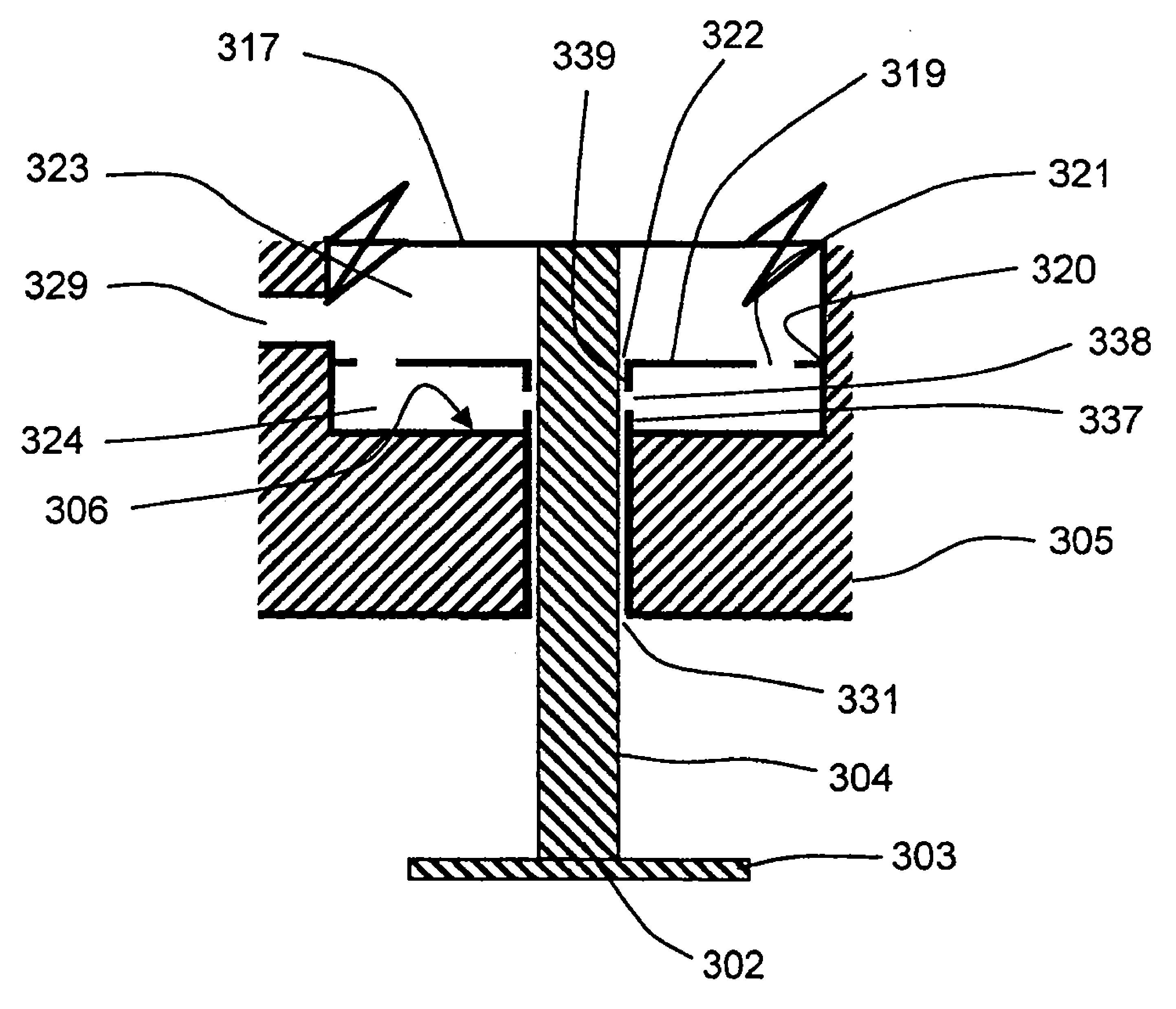
[0046] figure 1 The essential components of a purge valve 1 according to a first embodiment for letting off exhaust gas upstream of a turbine (not shown) of an exhaust-gas turbocharger (not shown) are shown. The valve element 2 comprising the valve disk 3 and the valve stem 4 is guided with its valve stem 4 into the valve housing 5 . The valve housing 5 is fitted to the exhaust housing 8 in which the exhaust channel 9 and the bleed channel 10 are integrated. The exhaust channel 9 and the bleed channel 10 are connected to each other via an overflow opening 11 into which the valve seat 7 is inserted. The valve disk 3 interacts with a valve seat 7 in the overflow opening 11 . At least one spring 12 in the spring chamber 13 of the vent valve 1 is braced between the cover 14 of the vent valve 1 and the support 15 of the diaphragm 17 . Because the bracket 15 is coupled to the valve stem 4 , the spring force is transmitted to the valve element 2 . In the non-actuated state of the...


PUM


Abstract

A relief valve for turbines of exhaust turbochargers. Hot exhaust gas flows against this type of relief valves and the relief valves heat up significantly. Sensitive components such as the springs or the membrane can be damaged as a result. The relief valves are normally designed so that the membrane and a radiation panel are adjacent to a first chamber. Air is continuously guided through the first chamber in order to specifically cool the membrane and protect the membrane from excessive heating.

Description

technical field [0001] The invention relates to an air bleed valve for a turbine of an exhaust-gas turbocharger with the features of the preamble of claim 1 . Background technique [0002] An exhaust-gas turbocharger for an internal combustion engine usually consists of a turbine and a compressor. The turbine is usually driven by the exhaust gas of the internal combustion engine, and the turbine rotor is connected to the compressor rotor in any way so that rotation of the turbine rotor causes rotation of the compressor rotor. The compressor rotor supplies the compressed combustion air to the associated internal combustion engine. The problem with this type of turbocharger is that the rotational speed of the turbine rotor and thus the compressor rotor increases with the rotational speed and / or load of the internal combustion engine. At very high operating speeds or loads of the internal combustion engine it may be the case that the turbine and the compressor are driven at t...

Claims


Application Information

Patent Timeline
Patent Type & Authority Applications(China)
IPC IPC(8): F02B37/18F15B15/10
CPCF02B39/00F04D27/0207F15B15/10Y02T10/144F02B37/183F02B37/186F04D27/0215F04D27/023Y02T10/12Y10T137/6579
Inventor M.多布罗沃尔斯基
Owner ROLLS ROYCE SOLUTIONS GMBH
Why Eureka
Try Eureka