Optical fiber winding-up machine

A wire take-up and optical fiber technology, which is used in the transportation of filamentous materials, thin material processing, transportation and packaging, etc., can solve the problems of poor wire take-up effect and high labor cost, saving labor, protecting optical fibers, and optical fiber distribution. uniform effect

Inactive Publication Date: 2014-01-15
成都亨通光通信有限公司
View PDF4 Cites 4 Cited by
  • Summary
  • Abstract
  • Description
  • Claims
  • Application Information

AI Technical Summary

Problems solved by technology

[0003] The purpose of the present invention is to overcome the deficiencies of the current technology and provide an optical fiber take-up machine to solve the shortcomings of the existing manual take-up, such as high labor cost and poor take-up effect

Method used


Image

  • Optical fiber winding-up machine

Examples


Embodiment Construction

[0012] Below in conjunction with embodiment the present invention is described in further detail, but structure of the present invention is not limited to following embodiment:

[0013] 【Example】

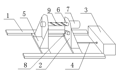
[0014] Such as figure 1 As shown, the optical fiber take-up machine includes a track 1, a pulley 2 and a pulling device 3. The pulley 2 is slidably arranged on the track 1 and connected to the pulling device 3 through a stretch rod 4. The pulley 2 includes a base 5 And the rotating shaft 6 installed on the base 5, the rotating shaft 6 is driven to rotate by the rotating motor 7 installed on the base 5.

[0015] The said rotating shaft 6 is provided with a raised pattern 9, which is used to block the take-up spool.

[0016] The control terminals of the traction device 3 and the rotating motor 7 are connected to a microcontroller.

[0017] A displacement sensor 8 is provided at the position facing the rotating shaft 6 on the pulley 2 for sensing the thickness of the optical fiber, ...


PUM


Abstract

The invention discloses an optical fiber winding-up machine. The optical fiber winding-up machine comprises a track (1), a sliding trolley (2) and a traction device (3), wherein the sliding trolley (2) is arranged on the track (1) in a sliding mode and is connected with the traction device (3) through a stretching rod (4), the sliding trolley (2) comprises a base (5) and a rotating shaft (6) arranged on the base (5), and the rotating shaft (6) is driven to rotate through a rotating motor (7) arranged on the base (5). The optical fiber winding-up machine has the advantages that a winding-up barrel is driven to rotate through the motor to conduct winding-up; besides, the traction device is used, the thickness of an optical fiber is sensed through a sensor, the transverse moving speed of pulling the winding-up barrel is calculated, and therefore the optical fiber can be wound on the winding-up barrel uniformly; thus, a great deal of labor is saved, and the optical fiber is distributed uniformly, will not be knotted during paying off, and is protected.

Description

technical field [0001] The invention relates to an optical fiber take-up machine. Background technique [0002] The take-up is the last link in the production of optical fiber. Generally, the take-up drum is manually turned to take up the wire. The optical fiber is in a mess, which has caused great harm to the optical fiber itself, and it is easy to knot when paying out, thus damaging the optical fiber. Contents of the invention [0003] The purpose of the present invention is to overcome the deficiencies of the current technology and provide an optical fiber take-up machine, which solves the shortcomings of the existing manual take-up such as high labor cost and poor take-up effect. [0004] The present invention is achieved through the following technical solutions: the optical fiber take-up machine includes a track, a pulley and a traction device, the slide is slidably arranged on the track, and is connected to the puller through a stretch rod, the pulley includes a ba...

Claims


Application Information

Patent Timeline
Patent Type & Authority Applications(China)
IPC IPC(8): B65H54/02B65H54/28B65H54/46
Inventor 孙义兴何吉焱许建国陈曲刘东陈治均
Owner 成都亨通光通信有限公司
Why Eureka
Try Eureka