Supercharge Your Innovation With Domain-Expert AI Agents!

Fastening system for wind turbines and corresponding installation method

A wind turbine and fastening technology, which is applied in the control of wind turbines, wind turbines, wind turbine components, etc., can solve problems such as increasing frequency and times, damaging star-shaped holes, and adjusting losses.

Inactive Publication Date: 2014-01-15
GAMESA INNOVATION & TECH SA
View PDF11 Cites 3 Cited by
  • Summary
  • Abstract
  • Description
  • Claims
  • Application Information

AI Technical Summary

Problems solved by technology

If the mechanism were to experience some failure of the bolts in the joint between the affected quill and quill flange, but continue to operate despite the broken bolt in that joint, the resulting wear would produce a significant loss of material on the quill which would Damage to the internal geometry of the holes in the star
This will cause a loss of alignment between the two components, thus increasing the frequency and number of such failure events

Method used


Image

  • Fastening system for wind turbines and corresponding installation method
  • Fastening system for wind turbines and corresponding installation method
  • Fastening system for wind turbines and corresponding installation method

Examples


Embodiment Construction

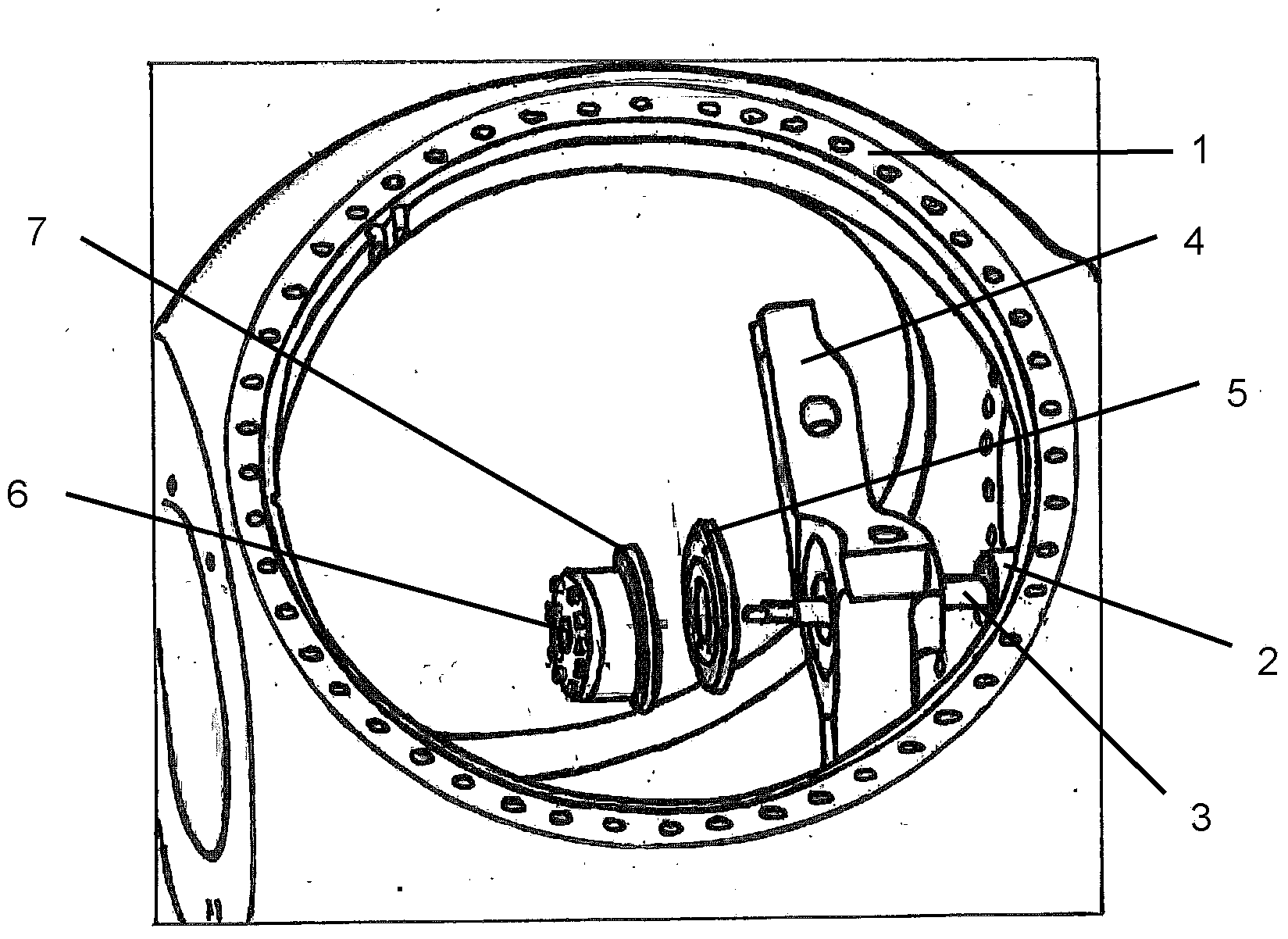
[0022] figure 1 Reflecting the current state of the art, the rotor comprises two components, the hub 1 and the blades (not shown in the figure). The wind turbine model of the present invention is a three-bladed variable-pitch machine, the blades of which are coupled to the hub by bearings. The blades are moved by hydraulic actuators which move the propeller shaft 3 linearly. This propeller shaft 3 simultaneously changes the pitch angle of the three blades while moving forwards and backwards a part called a star 4 , which unites the three blades. The hydraulic cylinders are located within the wind turbine nacelle and therefore do not rotate synchronously with the rotor. A bearing 6 is placed between the propeller shaft 3 and the star 4 to avoid rotation of the cylinder and propeller shaft 3 when the rotor rotates. The bearings are mounted in a housing coupled to the star 4 such that the outer ring 7 of the bearing 6 is coupled to the housing and the inner ring of the bearing...


PUM


Abstract

A fastening system for wind turbines comprises a front flange (9) and a rear flange (8) which are joined together and supported on the hollow rotary shaft (2) and coupled to the pitch system comprising the bearings (6) for the shaft and the star-shaped part (4). The fastening method couples the rear flange (8) to the hollow shaft (2) with a tapered collar (10) and also to the front flange (9) through some spacer bushings (11). The collar (10) uses friction to transfer significant moments and axial stresses so as to improve the fastening system, and the direction of the bolts on the collar (10) and the bolts (12) on the spacer bushings (11) simplify inspection and maintenance tasks.

Description

technical field [0001] The invention relates to a fastening system for joining a hollow shaft to a pitch system using a flange. The invention also relates to a method for mounting the system on the hub. Background technique [0002] A wind turbine is a machine comprising a large number of mechanical components of various types subjected to constant stress. These components require regular maintenance, which often requires visual or physical inspection. The purpose of predictive maintenance is to identify the most stressed components in order to strengthen them, and its purpose is to eliminate faults and replace components after their failure. This is especially important if the failure of the component requires the use of expensive cranes for the aforementioned replacement tasks. [0003] A wind turbine hub houses a pitch system comprising a hydraulic drive unit that moves a propeller shaft inside a hollow shaft. The propeller shaft then moves the star, which transmits t...

Claims


Application Information

Patent Timeline
Patent Type & Authority Applications(China)
IPC IPC(8): F03D11/00
CPCF03D1/0691Y02B10/30F03D1/0658F05B2240/61F05B2260/79Y10T29/49332F16B2200/50F16B2200/506F03D1/0675Y02E10/72F03D1/065F03D7/0224
Inventor 丹尼尔·阿塔尔·洛伦特费尔南多·德拉斯·奎瓦斯·吉梅内斯费尔明·拉斯科斯·桑特斯特万佩德罗·穆纳里兹·安德烈斯
Owner GAMESA INNOVATION & TECH SA
Features
  • R&D
  • Intellectual Property
  • Life Sciences
  • Materials
  • Tech Scout
  • Unparalleled Data Quality
  • Higher Quality Content
  • 60% Fewer Hallucinations
Learn More